Currently, and for good reason, much attention is being focused on the conservation of energy. Compressed air, like electricity and gas, is an energy resource. It has often been referred to as the third utility. As with all energy sources, our global environment demands that it be conserved and used wisely.
In many plants that use compressed air, approximately 20% of all utility costs go to that expense alone. Plants with multiple shifts and high compressor horsepower levels report totals in the hundreds of thousands or even millions of dollars! Yet studies show that up to 55% of that expensive air is wasted or misapplied.
|
Compressed Air Consumption |
|
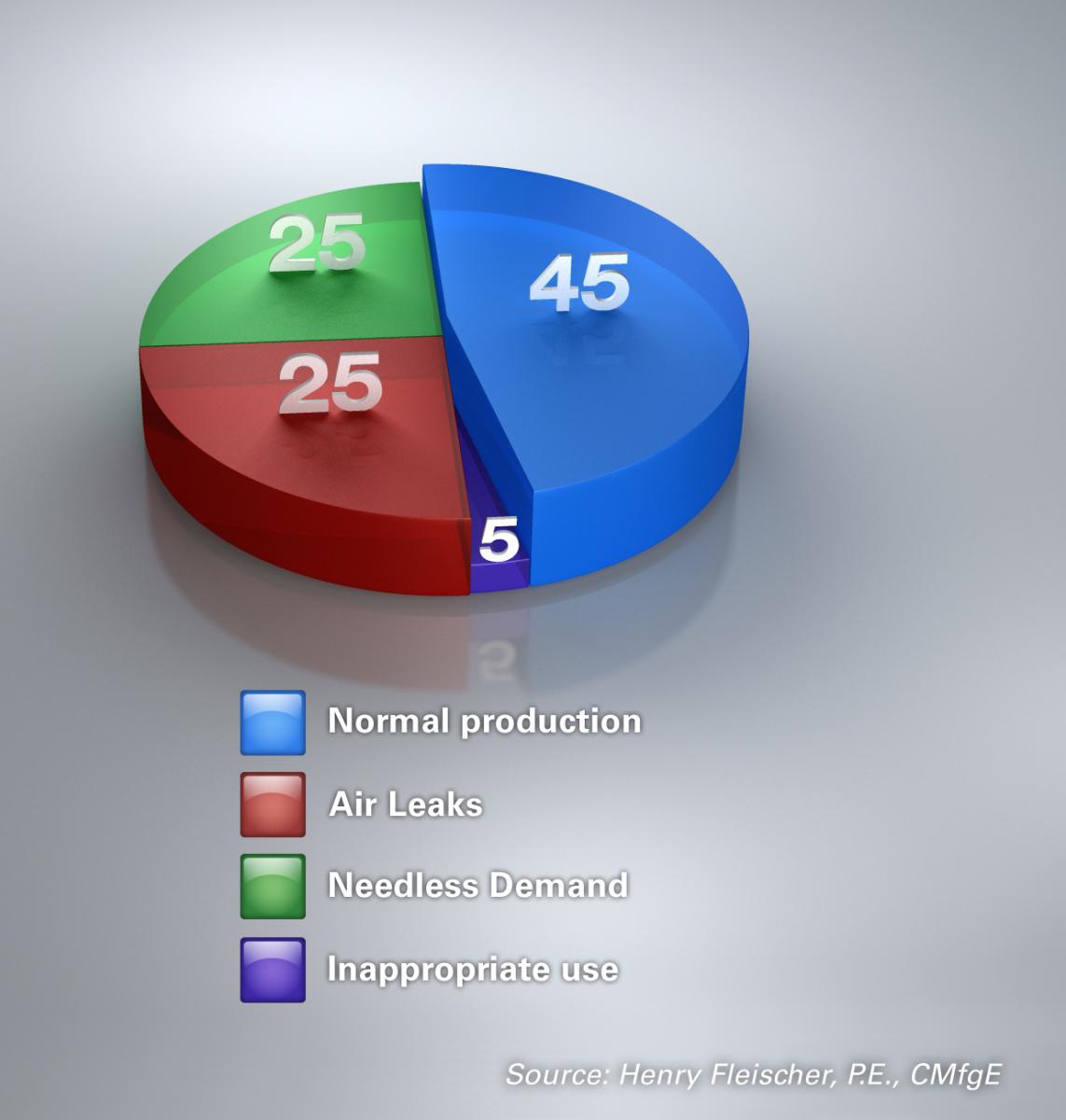
Component dimensions and operating pressures are very often wastefully oversized, creating needless demand and inflated operating costs. Blow-offs are continuous instead of intermittent forcing compressors to operate at excessive duty cycles or loads. Where dynamic seals are used, normal deterioration leads to air leaks. In our experience, we’ve found such examples of waste occurring in any given manufacturing facility many times over. The result is skyrocketing maintenance and energy costs.
One solution is to stop the “needless demand” by eliminating the practice of oversizing and over pressurizing pneumatic components and pneumatic circuits. With “energy conservation” being the primary objective, a typical pneumatic system (machine) that is optimized for component size and operating pressures can result in a 40-50% reduction in compressed air.
Many progressive companies looking for ways to address compressed air waste are conducting audits in their facilities. While numerous companies can be contracted to perform the service, the most comprehensive will include four key components:
- Step 1: Evaluation of supply efficiency. Establish a baseline. Identify the potential for energy savings starting with a complete evaluation of the compressor room. Determine the existing configuration, capacity, and condition of all existing compressor room equipment.
- Step 2: Detection of air leaks. Survey the air distribution system plant wide. Utilizing electronic leak detection instruments and flow meters, tag and quantify air leaks throughout the system. Pinpoint all leaks and estimate the total costs arising from leaks. Address inappropriate usage of compressed air.
- Step 3: Air quality analysis. Concurrent with leak detection, conduct a uniquely comprehensive air quality analysis of the compressed air supply throughout the facility. Examine factors from dew points to particulates to oil saturation levels. Document existing air quality and recommend filtration as appropriate.
- Step 4: Circuit analysis. Utilize proprietary “Circuit Analysis” software to optimize applications down to the component/equipment level. The analysis will produce recommendations for processes and products to reduce compressed air consumption while maintaining and often improving equipment cycle times.
Circuit Analysis: The Key Audit Component
In our experience, the “Circuit Analysis” is critical. By sizing all the pneumatic components of the air system, as well as selecting pressures to optimize its usage, the circuit analysis can significantly improve how a company manages its compressed air as an energy resource.
Pneumatic components are often measured in terms of their conductance — or Cv — defined as the capability of fixed orifice pneumatic devices to move air under differential pressure. In other words, the greater the Cv, the better the flow. System conductance refers to the total conductance of all the various pneumatic-circuit components. To achieve ideal performance, system conductance must be able to allow pressurization and exhaust of all stored air within the allotted time. Although increasing conductor sizes between the valve and actuator can improve conductance, it also increases the volume and ultimately compressed air usage. Therefore, increasing conductor size has both beneficial and detrimental effects on actuator performance times. Finding the right balance between the two is the key.
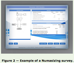
Case StudyNumasizing Surveys: Reducing the “Artificial Demand”Numasizing® is a proprietary technique from Numatics which enables compressed air to be used more efficiently by sizing all the pneumatic components of an air system, as well as selecting pressures to optimize its usage. Numasizing negates the need to speculate on the stroke time of an actuator even when subjected to two different loads under two distinct pressures.
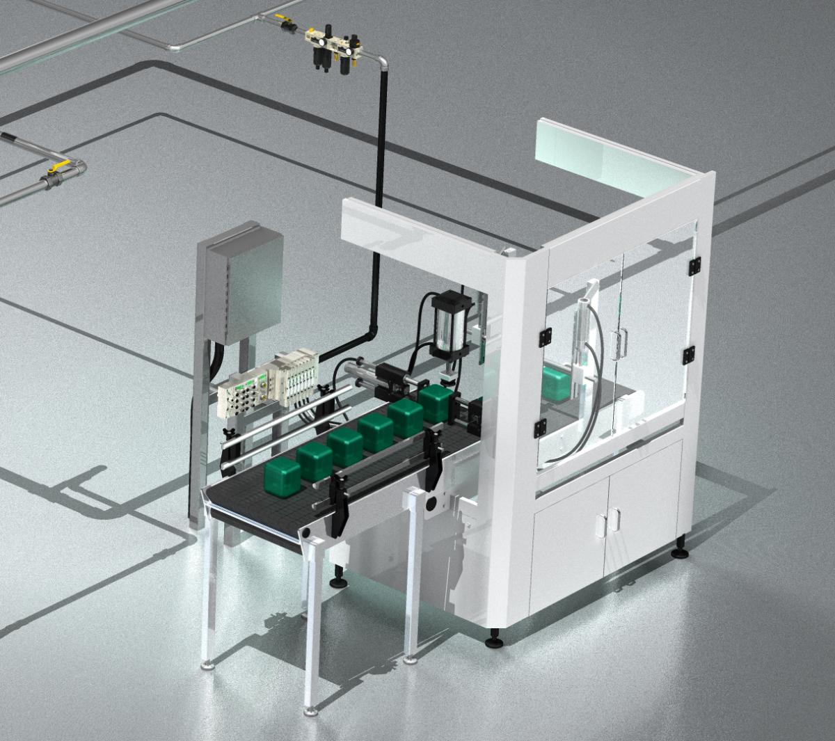
Figure 1 — Typical factory automation.Unlike other sizing programs, Numasizing is not rooted in a theoretical approach or a mathematical model. It is instead based on actual results of over 250,000 test firings of pneumatic actuators. Included in the program are actuators from 3/8" to 14" bores, operating in conjunction with different diameter/length conductors and valve sizes. The actuators were subjected to every conceivable dual pressure/load combination feasible. Consequently, this “built-in experience” allows Numasizing to predict and recommend components and pressures with confidence. The goal of any pneumatic design is to optimize components and fulfill customer objectives. Maximizing machine productivity may require larger valves operating at higher pressures. Whether the priority is reducing component size, maximizing productivity, or compressed air efficiency, proper component sizing and operating pressures can be determined. Unfortunately, there is not an ideal set of components or pressures capable of satisfying all objectives.
The survey indicated that the existing design utilizes a Numatics MK15 valve, with a flow coefficient Cv=1.5, operating a two inch bore cylinder. The pressure is 60 psig extend and retract, and the conductor is 1/2 inch rubber hose. After Numasizing, we determined that the proper cylinder bore size (to conserve compressed air) is 1.75 inches operating at 64.7 psig extend and 0 psig retract. The optimal conductor is 5/16 inch O.D. nylon tubing. A smaller valve was also optimal — a Numatics 2005 series, flow coefficient Cv=0.5. While the results showed that both scenarios satisfied the cycle time requirements, the Numasized arrangement predicted an annual consumption of \$116 of compressed air, as compared to \$209for the original design — a 44% reduction in compressed air cost. As compressed air is typically the highest utility expense in manufacturing facilities, reducing compressed air demand can generate a dramatic payback benefit. Numasizing can help by reducing the “artificial demand” present in most applications.
|
 In one recent Numasizing survey, our team focused on a valve and cylinder application within a material handling system. The system operates two shifts per day. The valve controls a six-inch stroke cylinder mounted vertically lifting a 60 pound load sitting on top of 40 pounds of tooling — 100 pounds total. The cycle time breaks down as: 0.5 seconds lift, 0.2 seconds dwell, 0.5 seconds lower and another 1.0 second dwell before the next cycle. The valve is mounted 72 inches from the cylinder. Those are the “fixed” details; everything else is subject to proper sizing. The questions were: What size cylinder? What size conductor (tubing or hose)? What operating pressure(s)? And so forth.
In our observations, OEM circuit designs typically select products based solely on the end customer production demands, rarely considering component size or energy management. Depending on the objective (or objectives), conductor size will change. Fortunately, for every conductor length, there is one optimum conductor size that can be determined to maximize performance. If the objective is to minimize component sizes, the optimum conductor will likely be different than the optimum conductor for high productivity. The same can be stated if energy conservation is the goal.
Actuator sizing behaves similarly to those of conductors. At a given pressure, increasing bore size generates higher forces to move loads. Doing so, however, results in an increased volume that must be filled and evacuated. This could impede performance times. Operating actuators at different pressures based upon load direction could create significant savings. This is evidenced by one example that we have all witnessed many times over: A cylinder used in a vertical application where the same pressure is applied to both extend (raise) and retract (lower) the load. Although there could be one bore size that optimizes productivity, there’s no rule of thumb for selecting bore sizes based on loads. In our recommendations, we rely on our own proprietary engineering tool — Numasizing® — to assist engineers in determining the optimum size.
More than 90% of factories around the world use compressed air. In a typical manufacturing plant, only about half of the compressed air generated is used productively. Undertaking the disciplined process of a pneumatic circuit analysis will return the best strategy for all departments within the plant, including Energy Management, Production, and Plant Engineering.
About the Author
Clint has been in the field of Fluid Power and employed by ASCO Numatics for over 30 years. During this tenure he has held positions in Manufacturing Engineering, Field Sales and Sales Management. Clint has worked with both OEM and end user customers providing recommendations to optimize equipment performance. Reach Clint Hodge, Pneumatic Specialist, ASCO Numatics by phone at 248-640-2225, or by email. www.numatics.com.
To read more System Assessment articles, visit www.airbestpractices.com/system-assessments.