A large mining complex in a remote northern region of the world invited a compressed air auditor in to assess the efficiency of a problematic system. Site personnel and their air compressor supplier were concerned a system in one of the buildings was not running optimally, and wanted to know what size of compressor to install in the facility. The auditor found significant savings in this target system, but even larger potential savings were found in other ancillary systems in the complex, as part of an extra investigation conducted while at the site. Overall, the potential energy savings total more than half of a million dollars, if all recommendations are implemented. Due to the remote location, this facility pays a significant cost per kWh, therefore, potential project paybacks are very attractive.
Initial Findings at Rock Crushing Target System
A rock crushing facility, one of many separate systems on the mine site, has a compressed air system consisting of two air-cooled screw compressors, one 250 kW (325 hp) 7.4 bar rated lubricated fixed speed for a plant air system, and one 45 kW (60 hp) 7.5 bar rated oil free compressor for a separate instrument air system. Historical operating hours show, until a few years ago, the small 60 hp oil free compressor fed the complete plant most of the time. A dewpoint controlled heatless dryer rated at 297 cfm conditions the instrument air. Only the instrument air used in the plant is passed through the dryer, the general plant air is undried. The dryer has a general-purpose coalescing filter installed before the air dryer, and a particulate filter on the outlet. Check valves exist at the discharge of the air compressors and between the plant and instrument air systems to prevent wet air from contaminating the dry instrument air.
The compressors and dryer are located in the basement area near a crushed rock unloading area, with poor air quality and ventilation. As a result, there is a fair amount of dust on the compressed air equipment. The compressed air is directed through the plant processing area by a system of steel piping.
A large 3,800-gallon wet receiver tank is located in the compressor room at the discharge of the large compressor. A 1,060-gallon dry receiver is located at the outlet of the air dryer for this instrument air compressor. The condensate drains used in the facility are timer drains. Most of the pressure loss in the facility is across the drying and filtering system. Leakage detection was done with only a few small leaks noted, nothing significant was found, and as such not reported. The plant personnel are doing a good job finding and repairing leaks.
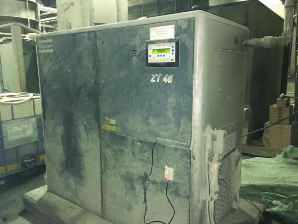
Figure 1: The dusty environment causes maintenance issues at this site.
Compressed Air System Baseline
The compressed air system’s electrical power consumption was monitored using data loggers connected to the compressors. System flow has been calculated using compressor rated flow (from compressor nameplate), and multiplying by the compressor duty cycle (no flow meter was installed). Pressure loggers measuring pressure gradient were located at the compressor discharge and after the air dryer and filters. The captured baseline is shown below:
Rock Crushing Facility Baseline
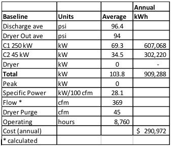
Baseline
Based on the baseline energy consumption the site electrical cost, the typical annual operating cost of this system would be about \$291,000 per year.
The readings and observations during the measurement period showed the air compressor(s) are producing compressed air at a poor efficiency of 28.1 kW/100 cfm (normal is about 20 kW/100 cfm). This poor specific power is caused by excessive unloaded run time of both compressors. The actual plant loading is only slightly above the capacity of the 45 kW compressor, yet the only other available unit is a 250 kW compressor. The 250 kW compressor spends most of its operating hours in the unloaded condition, because it is much too large for the average flow. Compressor control settings limitations, actual pressure bands and the presence of check valves makes this problem worse because the small compressor also runs partially loaded at the same time. During some unnecessary purge operations, problems with the uncontrolled dryer purge control consume additional compressed air. Poor compressor room ventilation, and the presence of excessive dust is also causing less than optimum ambient conditions, as well as compressor shutdowns.
Air Compressor Master Controls to Prevent Control Gap – Webinar RecordingDownload the slides and watch the recording of the FREE webcast to learn:
|
Compressed Air System Operating Profile
The following graphic shows a profile of the compressed air crushing system operations over the last part of the measurement period. During this time the 250 kW compressor was manually shut down between production cycles to save energy. Although this is an excellent practice, there are multiple periods of time where the plant flow exceeded the capacity of the small compressor. This causes the pressure to fall to low levels, because the 250 kW unit is not in automatic and could not start to support the pressure. During this time, the small compressor was operating quite efficiently, because a fixed speed compressor should be running near full capacity.
When the two compressors were both running together the system efficiency fell to low levels. The existing control settings and the check valves caused both compressors to operate in part load condition at the same time. This caused significant periods of unload run time for both compressors.
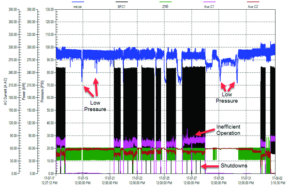
Figure 2: Compressed Air Profile During Measurement Period. Click here to enlarge.
Compressor Control Problem
Analysis of the captured data shows, in normal operation, the plant compressed air demand is only slightly above the capacity of the 45 kW instrument air compressor (240 cfm). Peak demands during the measurement period were as high as 500 cfm. When the compressed air demand increases over the capacity of this small compressor, the only option to maintain adequate pressure is to start the large compressor and run it lightly loaded. Unfortunately, when the large compressor runs, the check valves block the actual system pressure from reaching the small compressor control. This causes the small compressor to keep running inefficiently by loading and unloading at the same time. Essentially, a large 1,600 cfm compressor is started to feed a 100 to 200 cfm shortage of compressed air.
The table below shows the operation profile and the compressor pressure setpoints.
Compressor Setpoints
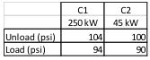
These settings make the large compressor the lead unit whenever it is active.

Figure 3: Both compressors are loading and unloading at the same time. Click here to enlarge.
With these setpoints, the small compressor should normally turn completely off when the large compressor runs, minimizing its wasted unloaded run power. However, due to the check valves at the compressor discharge and before the plant air wet tank, the small compressor cannot “see” the true system pressure when it unloads. Leakage in the compressor supply lines (the compressor condensate drain leaks) between the check valves, causes the pressure to fall at a faster rate than the actual plant air receiver pressure, as the air drains out of the lines. This causes the small compressor to reload at its 90 psi setpoint before the large compressor gets a chance to load at 94 psi. A special test was done, bypassing the check valves and tying the two compressors to the same header by opening a crossover line. When this was done the small compressor timed out and shut off, saving power.
It is very inefficient to run two compressors in load/unload mode at the same time to produce the air only one compressor could produce. In this mine’s case, it is also very inefficient to run the large compressor, rated at about 1,600 cfm, solely to feed about 370 cfm of average load. The unloaded run power of the large compressor (49 kW when no compressed air is being produced) is actually higher than the fully loaded kW of the small compressor (43 kW).
Normally, if the small compressor was in good condition, the recommendation would be to simply add a second 60 hp compressor to work with the existing unit. However, the existing compressor is in poor condition, so it would be best to replace it with a new compressor with a larger capacity and VSD control.
Some increased efficiency could be gained by controlling the system pressure to slightly lower levels of 90 psi. VSD control above minimum speed would maintain a constant plant pressure, reducing the compressor power, and slightly reducing the plant demand.
Potential Energy Conservation Measures
Some specific potential opportunities are as follows:
Recommendations:
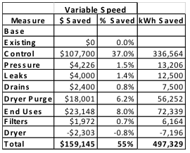
- Replacement of the 60 hp (45 kW) instrument air compressor with a new 110 kW (150 hp) VSD controlled compressor would save 336,600 kWh, annually worth \$107,700 per year in operating costs (37%).
- Remove the check valves from the compressor discharge and from before the plant air receiver. Run the system with the main crossover valve open to tie all compressor discharges together.
- Set the new VSD compressor to 90 psi (current average 96 psi) target pressure. This would save 13,200 kWh and \$4,200 in operating costs.
- Replace air powered vibrators with electric for \$21,500 annual savings.
- Repair faulty air dryer dew point control or replace air dryer with purgeless design, for \$18,000 annual saving.
- Upgrade system filters to mist eliminator or oversized design.
- Replace timer drains with more efficient airless drains.
- Upgrade ventilation to ensure compressors remain clean.
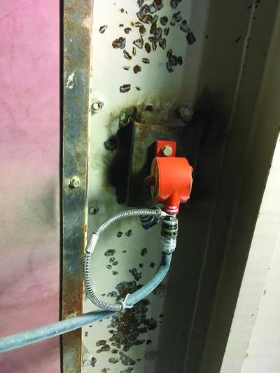
Figure 4: Air vibrators like this could be the reason a second compressor has to run.
Summary of Crushing Building Savings
Sufficient potential exists for up to an estimated 55% savings in compressed air operating costs over the present crushing building configuration. The installation of a 110 kW VSD compressor, low loss drains, the replacement of the air dryer with more efficient purge control, lower plant pressure and reduced inappropriate uses, would save an estimated \$159,000 per year in compressed air electrical operating costs.
A summary table of the estimated potential savings is as follows:
Investigation of Other Site Systems
While investigating the other systems in the complex, an initial survey of the compressor operating hours was done. It was found that many of the systems had a poor ratio of loaded to running hours. There may be excellent potential for additional savings over and above those found in the target system.
Some additional systems:
- Process Plant consisting of three 110 kW lubricated screw compressors (two main, one spare) with heatless desiccant instrument air dryer.
- Truck Shop general air system consisting of two 90 kW lubricated screw compressors (one main, one spare) with heatless desiccant dryer.
- Truck Shop tire fill system with two 45 kW lubricated screw compressors (one main, one spare) with heatless desiccant dryer.
- Powerhouse 1 starting air with one 37kW lubricated screw compressor, no dryer.
- Powerhouse 1 service air with two 37 kW compressors (one main, one spare) with heatless desiccant dryer.
- Powerhouse 2 starting air with one Quincy 37 kW modulating compressor and no dryer.
- Powerhouse 2 service air with two 37 kW compressors (one main, one spare) with internal refrigerant dryers.
- Batch plant with an 18 kW screw compressor and non-cycling refrigerated dryer.
Compressed Air System Baseline
The compressed air system electrical power consumption was monitored for eight selected systems, using data loggers connected to the compressors. System flow was calculated using compressor rated flow (from compressor data or on the nameplate), and multiplied by the compressor duty cycle (no flow meters were installed). The table below 2 shows the operation profile and the compressor pressure setpoints.
Baseline for Additional Systems
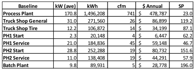
The readings and observations during the measurement period showed the air compressors were producing compressed air at poor efficiency for all systems, as noted by the specific power. Levels of around 18 to 20 are normal for an optimized system using large compressors of 100 hp or greater. For smaller compressors, levels 20 to 25 are normal, depending on the discharge pressure.
In general, the specific power relates to the compressor operating mode. For load/unload compressors the ratio of compressor loaded run time, compared to the total operating hours (loaded plus unloaded) determines the specific power. In order to achieve lower specific power with this mode, the unloaded run time must be minimized either by running the compressors in start/stop mode or installing a properly sized VSD compressor. In systems with multiple compressors, only one VSD compressor is required for the complete system. This VSD compressor should be equal to, or larger than, the fixed speed compressors to avoid undesirable control gap problems.
For compressors running in modulation mode (PH2 starting air and Batch Plant), the least efficient way to operate a screw compressor, the system can be optimized by running the existing compressors in start/stop mode. This can be done by providing very large storage and a wide pressure band, if they have the capability of doing so. The PH2 start compressor does not appear to have the internal circuitry for this. The Batch Plant compressor had the correct electronic control, but the compressor needs to be replaced due to mechanical problems. The simplest and most effective way to optimize this system, is to simply install a VSD compressor and a cycling dryer. The compressor installed on the PH1 starting air system is an example of a unit running in start/stop mode due to large storage. It should be noted its annual operating cost is significantly lower than all the others. Some further tweaking of the compressor settings on PH1 could gain even more savings by eliminating the remaining small amount of unloaded run time.
Uncontrolled operation of desiccant air dryers is another reason for high operating costs and low efficiency. If you compare the flow produced by PH1 Service compressors to the PH2 service, the difference in flow, 45 cfm to 20 cfm, is due to malfunction of the PH1 desiccant air dryer purge control. This is likely due to the poor condition of the onboard dew point probe.
Compressed Air System Operating Profiles
In essence, all systems monitored were operating in load/unload mode with timed shutdown, except for the PH2 starting air and the Batch Plant. Internal to the control of the compressor type installed in most systems, is a starts per day setting. This allows a certain set maximum number of starts per hour, and will completely turn off the compressor. This eliminates unloaded run time between load cycles, if the compressor has not exceeded the maximum number of starts. This can completely eliminate the unload run time, saving power. The allowable number of starts per hour varies depending on the compressor size, for example, smaller compressors are capable of more starts. This feature can be used with the existing large storage receiver capacity and a wider pressure bands to completely eliminate wasteful unloaded run time for all small compressors, about 75 hp and below.
For larger compressors (Process Plant and Truck Shop Service Air), the only option is to install a VSD controlled compressor in each system, or run a combination of smaller compressors (one being a VSD) matched to the existing fixed speed units. Generally, the installed VSD unit should be one size larger than any installed fixed speed units to prevent a condition called control gap, where the compressors fight for control.
Potential Energy Conservation Measures
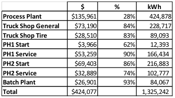
Analysis of the information collected showed potential opportunities existing, that could result in significant reductions to the energy consumption of the compressed air system. These reductions in the energy consumption could potentially save about \$424,000 per year in annual electrical costs.
Extra Savings Summary
An example of the savings that can be gained is shown in the following profile of the PH1 starting system compressor operation (Figure 4). It can be seen, other than a few cycles of extended unloaded run time, the compressor loads and then completely shuts off, reducing the wasteful run time. This is the reason this system has significantly lower costs than all the others. The occasional periods of unloaded run time could be eliminated by simply widening the compressor pressure band or adding storage receiver capacity. As an example, the PH2 starting system is running at less than 10% capacity, yet consuming about 70% of full load power (Figure 5).
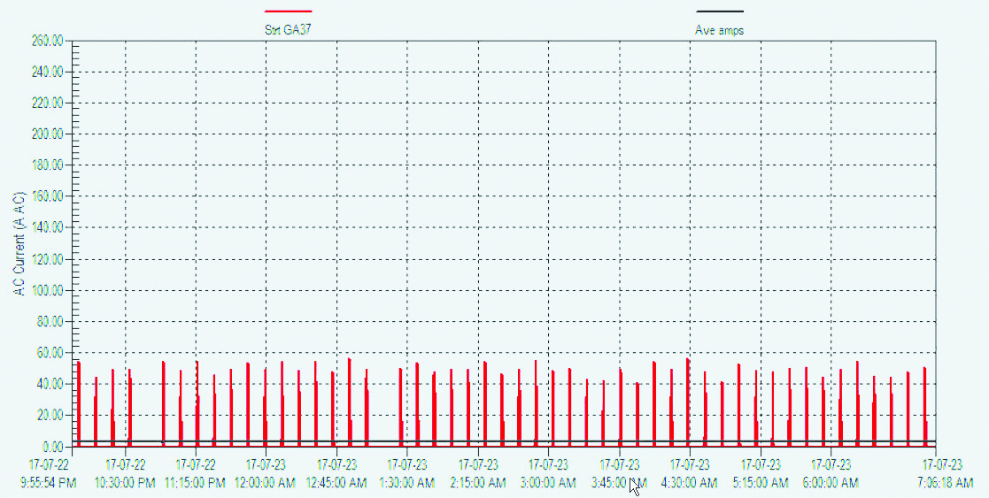
Figure 5: PH1 Starting compressor has very little unloaded run time in start/stop mode. Click here to enlarge.
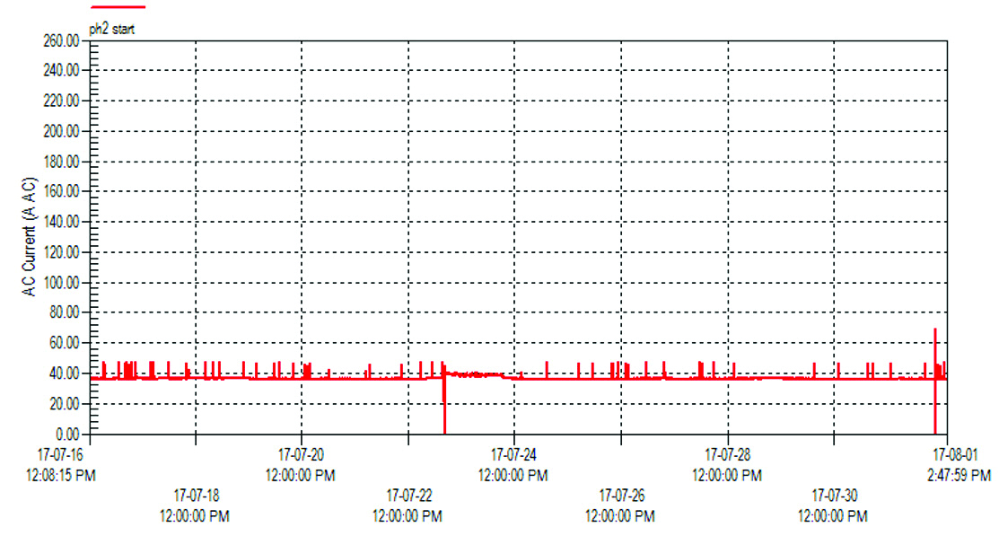
Figure 6: PH2 modulating compressor consumes constant power even at light loads. Click here to enlarge.
Basic energy conservation measures recommended in these systems:
- Installation of properly sized VSD compressors in each large system, 90 kW and above.
- Operation in start/stop mode with large storage for smaller systems.
- Repair or recalibration of faulty air dryer dew point controls.
- Better operation of internal refrigerated dryers so they shut off with compressors.
- Replacement of timer and manual drains with airless style.
A summary table of the estimated potential savings is as follows:
Conclusion
About \$580,000 total, in potential energy savings were identified in only a few days of study. This is just as effective in generating profits as finding a large chunk of a valuable resource, like gold or diamonds. If implemented, the energy conservation measures generate these savings year after year. This is a good example of what can happen when a system is assessed with instrumentation. Plans at this site are to have a closer look at the mine air, and some other additional systems, to see if more savings can be gained.
For more information contact Ron Marshall, Marshall Compressed Air Consulting, tel: 204-806-2085, email: ronm@mts.net
To read more about Air Compressor Control System Assessments please visit, www.airbestpractices.com/system-assessments/compressor-controls.