Basic Operating Theory of a Pulse Jet Dust Collector
The dust is collected on the bag or fingers, and when the cake of dust is of appropriate thickness and structure, a pulse or pulses of compressed air hits or shocks the bag and knocks the cake off. This pulse may sometimes be accompanied by physical shaking and even reverse air flows, depending on design.
When the cake is removed correctly from the dust collector, the system removes dust from its assigned environment and has a normal bag life. When the cake is not removed efficiently, the dust collector does not remove dust effectively from its assigned environment and the bag life can be significantly shortened.
Dust collection system designs specify the compressed air inlet pressure to the manifold and pulse valves necessary for effective dust removal. The pulse valve sends a given volume or weight of air to the bag at a predetermined velocity to strike and clear the cake. The actual amount of weight of air is dependent upon the pulse nozzle being fed compressed air at a pre-determined and steady pressure. The dust collector must receive the correct pressure (or close to it) and a steady repeatable pressure level for each pulse, particularly if timers are used to control the pulses. The operator may experiment to find the "right timing sequence" at a desired compressed air inlet pressure. However, if this pressure varies, then performance will not be consistent or satisfactory.
Dust Collector Reverse Flow Filter Pulse Cleaning
The reverse flow filter dust collector utilizes cartridge elements which are cleaned by “back flushing” with compressed air. This momentary air flow reversal is induced by a short burst of compressed air similar to pulse jet sock or bag filter. The compressed air is released from the storage receiver by a fast-acting high flow diaphragm valve. This “pulse” of air dislodges the accumulated dust from the element. The dust then dumps into the “hopper” or collector drawers.
Each pulse cleans a series of filter elements leaving the remaining cartridges available to continue filtering the air. Each diaphragm valve typically operates one pulse jet blow pipe. Each pulse jet blow pipe contains a nozzle for each cartridge – usually up to three cartridge filters per pipe. As the pulse of air reaches the nozzle it is accelerated through the smaller diameter creating a low pressure center, or Venturi, pulling in surrounding air through the filter in a counter-flow direction.
The rated flow of compressed air per pulse is often 3 to 6 cubic feet (this may vary at any site and the proper data will be needed), with normal pulse duration of 0.15 to 0.5 second, and one valve opening every 15 seconds. Obviously there are other designs with different specifications. Most of the time there will be only one valve opening every 15 seconds but sometimes there could be two or more pulses simultaneously.
Installation Considerations for Proper Compressed Air Supply
Short bag life usually comes from the pulsers hitting the bag when the cake is not ready to flake off or the cake has gone too long between pulsing and has grown too thick and heavy to clean effectively. This causes not only short bag life, but also very poor performance. There are several possible causes for this, including:
- Incorrect timer settings for the operating conditions. The actual requirement for the optimum timer setting may well change as various product runs change, or this may change seasonally. These settings have to be set carefully during initial installation and then monitored regularly
- Lack of sufficient compressed air storage near the inlet manifold to supply the required pulse air without collapsing the inlet pressure. With too low an inlet pressure, the mass weight of the air pulse is too low, which then becomes ineffective in removing the cake
- Too small a feed line to the dust collector entry will have the same effect as lack of air supply
- Too small or an incorrect regulator, which is unable to handle the required rate of flow required by the dust collectors
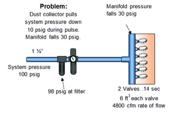
The picture below illustrates a common installation or system situation that causes restricted compressed air flow. Prior to the installation or operational change, the proper rate of flow was not identified for the dust collector cleaning action. Feed line sizing, regulator sizing, and air supply all require an identified rate of flow. Using average flow rate instead of the rate of flow can be misleading and typically results in misapplications. This is true for both Pulse Jet and Reverse Flow.
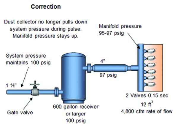
How to Correct for Pressure Drop
Improper compressed air delivery and supply may create an ineffective pulse. This can be addressed by:
• Using proper line size to handle rate of flow without high pressure loss
• Using storage to supply air without pulling down feed to the receiver/collector
• Monitoring inlet pressure and drop at pulse
• Monitoring flow
Rate of Flow
Flow rate is the average flow of compressed air in cubic feet per minute either required by a process or delivered to the system. Rate of flow is the actual rate of flow of compressed air demand expressed in cubic feet per minute regardless of duration. Even relatively small air demands in cubic feet can have a very high rate of flow, if they occur over a very short time period. Dust collectors normally have this characteristic.
Sequence controllers can have a very significant impact on the required rate of flow. For example, the following table illustrates a dust collector system which has six pulsing valves that use 3.5 ft3 over ½ second for each pulse. When this is a problem, appropriate storage and piping can be an effective correction when properly implemented.
Example Rate of Flow Calculation
|
Typical sizing (each valve uses 3.5 scfm/pulse – 6 valves on collector) |
|
|
Rate of flow and sizing with one valve hitting every 7 seconds |
Rate of flow and sizing with six valves opening at once every 7 seconds |
|
Rate of Flow = (1) × (3.5) = 3.5 × 60 ÷ 0.5 = 420 scfm |
Rate of Flow = (6) × (3.5) = 21 × 60 ÷ 0.5 = 2,520 scfm |
|
The line size recommendation from the air supply to the dust collector – 90 psig line pressure = 2” to 3” |
The line size recommendation from the air supply to the dust collector – 90 psig line pressure = 4” to 6” |
|
|
The impact of two different rates of flow shows similar differences in regulator sizing if they are used on the feed line flow. The high flow velocities entering the manifold and controls for the pulse valves will create extra pressure loss through the nozzle, affecting the performance of the pulse cleaner. The same effect would show up in air receiver sizing to minimize both system and feed line pressure drops, if that is a question.
The table below provides an example of how to calculate storage size. The following figure illustrates how to apply this storage to lower the rate of flow.
Example of Calculating Storage Size
| Pulse rate of flow to dust collectors | |
|
Objective: Size storage to allow pulse of 21 ft3 in |
|
|
6 valves × 3.5 ft3 = 21 ft3 21 ft3 × 60 sec ÷ 0.5 sec = 2,520 scfm rate of flow |
|
|
Calculating storage size |
|
|
T = Time (seconds) V = Volume storage (ft3) C = Capacity scfm (2,520) rate of flow Pa = Psia (14.5) P1 = Initial receiver pressure (100) P2 = Final receiver pressure (96) |
V = (C) (Pa) . |
|
V = (2,520) (14.5) . |
|
|
V = 36,540 |
|
|
V = 76 ft3 76 ft3 × 7.48 gallons/ft3 = 568 gallons or more receiver size required |
|
|
Calculating 7-second refill rate of flow: |
|
Time allowed = 6 sec 21 ft3 × 60 sec ÷ 6 sec = 2,109 scfm rate of flow Effect on header: Negligible |
Storage to Decrease the Rate of Flow
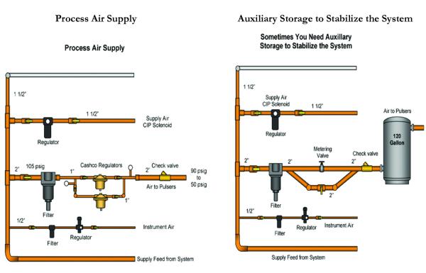
Click to enlarge.
Additional Dust Collector Installation Guidelines
It is recommended that every feed line have a quality pressure gauge installed near the dust collector entry. Observe the pressure gauge when the pulser hits. If the pressure drop is too high (over 10 20 psig), start looking for the cause. Record the specifications on the dust collector (scfm per pulse, feed line pressure, time per pulse, cycle time between pulses). Calculate the rate of flow and check line size and storage. If additional storage is required, it can be calculated by using the formulas presented in the “Example of Calculating Storage Size” table shown previously.
The sequence and pulse jet nozzle size depend on the number of bags, type of bags, length of the bags, and the materials being trapped. These will vary by make and model. Some rules of thumb that often apply:
- ½ second is commonly used for the pulse duration.
- Air flow per pulse jet is very often from 3.5 ft3 to 10 ft3.
- Dust collector capacity is often increased first by lengthening the bags and/or increasing the number of bags in the housing.
- As the bag length increases, the pulse jet air demand increases. In one example, increasing from 18" length bags to 84" length bags increases the pulse demand about 25% incrementally.
- As the number of bags of the same design increases, the pulse air required increases by about the same percentage.
The number of pulse jets, sequence, and air demand need to be known to install any dust collector correctly to ensure an adequate flow of compressed air at the proper pressure.
With the variety of filters of modern high-performance materials available today, many operations are modifying their older dust collectors; however, too often the effect on compressed air requirements is not considered.
Compressed Air Leaks in Dust Collectors
Pulse jet dust collectors are a continuing source of leaks, particularly when pulse jet diaphragms fail which can create a very large compressed air leak. An open 3/4" diaphragm pulse valve can leak up to 200 250 scfm, equivalent to 50 to 60 hp worth of compressed air, and costing about $24,000 /year.
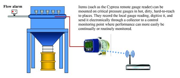
Often, these failures/leaks are hard to hear and sometimes, when first heard, are ignored in the hope that someone else will notice and repair it. After all, it is a hot, or cold, dusty, noisy job, often high above ground level. There are some excellent electronic monitoring systems available which will identify leaks from failed solenoid pulse jet valves. These can also monitor filter performance and condition and monitor the system’s capability to stay in compliance.
For these monitoring systems to perform as designed, the compressed air supply should deliver solid, consistent pressure at the point-of-use. A paddle switch visual alarm can easily be installed on the air supply pipeline. Whenever the paddle sensor sees compressed air flow, the light turns on. When the pulse jet hits, the light turns on and then turns off when it closes. If the light stays on, there is continuous flow – a leak!
Automatic Pressure Differential Pulse Controllers
A demand-side controller is always suggested for properly installed applications. This senses the filter condition and only pulses the bag at the right time. There are some excellent electronic control systems available which can be very economical and will usually improve bag life and reduce air usage.
Projects, which are very effective in optimizing compressed air usage, are always recommended; however, the storage and piping has to be correct for proper operation. When not installed properly, there can be a significant negative impact.
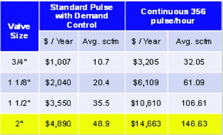
The following table (supplied by FilterSense) indicates estimated compressed air savings based on valve size for a 10 row pulse jet dust collector with either a pressure differential control or timer control set at 356 pulses /hour.
Compressed Air Use for a 10-row Dust Collector
When a plant or operation with significant dust collecting is reviewed, it is very rare to find an operator who is aware of what the dust collector’s operating specifications are and how or why the pipe sizes were selected. Typically, when returning conditions to the originally manufactured specifications, the unit will run as intended.
Dust Collector Troubleshooting and Maintenance Tips
All dust collectors need routine maintenance of clearing plugged tubes, in addition to:
- Continuous diaphragm/valve repair
- Cleaning and checking magnehelic gauges and other critical sensors
- Reset timers, if required
When pulse valve diaphragms become worn and do not seal, filter cleaning becomes ineffective and often the operators adjust the timers to a more frequent cycle, which offsets the lack of performance. This is a poor practice.
Generally speaking, all diaphragms should be replaced within a 3 to 5 year period. Ideally, when replacing one, replace them all. Obviously, different operating condition and controls will yield varying results.
Proper operating valves and diaphragms will allow better filter cleaning, reduce particle emission and use less compressed air:
- A 3/4" ASCO-manufactured pulse valve diaphragm kit retails for about $20 to $25 each
- A 3/4" pulse valve leak may well be as high as 200 scfm. The 1 ½” and 2” valves can and do leak up to 1,000 scfm
- Monitor all control sensors (Δ pressures, time delays, cycle times and cleaning times) per manufacturer specifications
- If pulse cleaning never stops when it should, then:
- Check if the pressure tubing is disconnected
- Check electrical connections
- Check high and low pressure points
Diaphragm and valve maintenance is often overlooked in many plants until losses grow to the magnitude where there is not enough air to feed the hungry leaks, at which time a crisis arises, possibly leading to the purchase of additional compressed air. It is obvious that poorly operating, and even more so leaking, valves and diaphragms can use significant volumes of very expensive compressed air. It behooves any plant that operates pulse jet dust collectors to know them well and maintain them properly.
Conclusion
The preceding information is designed to help create clear operating guidelines for all plants to not only effectively use compressed air, a plant’s most expensive utility, but to also enhance continuing productivity and quality of overall plant performance.
For more information contact Hank van Ormer, Technical Director, or Don van Ormer, Senior Auditor, AP Energy (formerly Air Power USA) at tel: 740.862.4112, Visit https://apenergy.com.
To read similar articles on Compressed Air End Uses, please visit
https://www.airbestpractices.com/system-assessments/end-uses.
Visit our Webinar Archives to listen to expert presentations on Compressed Air Piping Design at https://www.airbestpractices.com/webinars.