Perhaps your facility recently had a compressed air system survey, conducted by an air systems services company, that resulted in a couple of major recommendations, such as:
- Install a new smaller compressor and new control systems on all of the units
- Repair the many air leaks (identified as 30% of your system capacity)
These capital-intensive recommendations could involve significant process system downtime, and possibly reduce air system energy costs marginally. Numerous such stories have been reported. Our experience (which includes more than 30 years of the technical evaluation of air systems from the ‘users’ perspective) has been that there are often more effective opportunities to evaluate, including:
- Piping system anomalies (engineering glitches)
- Equipment operational anomalies (process and maintenance glitches)
In many facilities, compressor systems often get little attention from engineering and maintenance staff because process equipment, electrical power, HVAC and steam systems normally occupy more of their time. The main technical priorities for a plant compressed air system should be:
- Manufacturing process reliability (air quality)
- Compressed air system cost control
How much do you spend for compressed air?
For \$0.10 power, a 1 horsepower motor costs \$2.00 per day to operate. Two 300 hp compressors would cost about \$1,200 per day for power and \$250 per day for operation and maintenance — that equates to over \$500,000 per year.
During visits to many facilities, we’ve discovered production areas that have incurred air pressure problems (reliability issues) and, as a result, utilities have raised the air pressure (cost increase). Remember the number one rule of thumb for air systems: A 2 psig increase at the compressor is a 1% power increase on the motor. We generally recommend that plant air compressors be operated at a maximum 90–95 psig.
Will your air system support the manufacturing process at this pressure?
If not, the first order of business should be to develop a generic piping schematic diagram for use in conducting a thorough system assessment — much like having an atlas highway map for a vacation trip. Generally, every facility has a fire system schematic piping drawing because the insurance carrier requires it. You should develop a similar drawing for your plant air system. It can be extremely useful in troubleshooting and identifying anomalies.
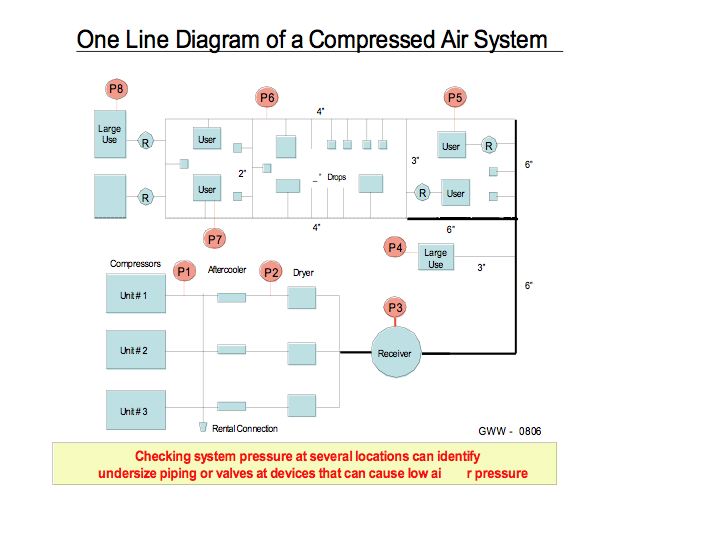
So, what compressor discharge pressure does your facility really need? The piping system design is crucial to operating the compressors at lower pressures. Piping configuration frictional line losses can be significant. Short-duration, high ‘surge-flow’ conditions also can affect system pressure.

Perhaps your plant recently experienced a major expansion, at which point engineering surely conducted an electrical load study and a fault current assessment. Did they also conduct a compressed air piping system study before installing another compressor? Or, did they just connect the new equipment to the nearest main air line and add a new compressor in the existing machinery equipment room?
Consider the following actual field examples:
1. A large tissue mill in the Midwest upgraded a packaging machine and added a new high-speed casepacker. Overnight, utilities needed to run a fourth 500 hp centrifugal compressor (the stand-by unit) to ensure that the casepacker would operate properly. Our investigation discovered 150' of ¾" steel air line supplying the machine, and ½" valves and pipe nipples at the 1" size air supply regulator on the unit. A contractor crew located the nearest blank connection on the 2" air headers in the bay to supply the new equipment. Reason: The mill did not want to take a system “down” to install a 1" connection on the air line above the machine. At \$0.06 power, the fourth compressor and air dryer were costing an additional \$600 per day. It took about 15 minutes to convince the mill manager to schedule a two-hour “down” for an air header connection near the new machine.
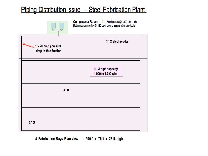
2. A steel fabrication plant had a 300 hp rotary compressor supplying air for two 500' long x 75' wide production bays. Two new bays were added adjacent to the first, and a second 300 hp compressor was installed, which sounds like a straightforward and logical plant expansion, right? Hardly! These compressors had to be operated at 125–128 psig to provide enough pressure in bays two, three and four. The process team thought that they might have underestimated air demand in the new bays, and were therefore considering a third unit. Instead, analysis identified that the 3" air line in bay one was experiencing a 20 psig pressure drop. Closing the loop at the far end of the bays allowed the compressors to again operate at 95–100 psig. A 20 psig lower pressure meant 10% savings: 40 KWh = \$30,000/year. Piping cost was \$15,000.
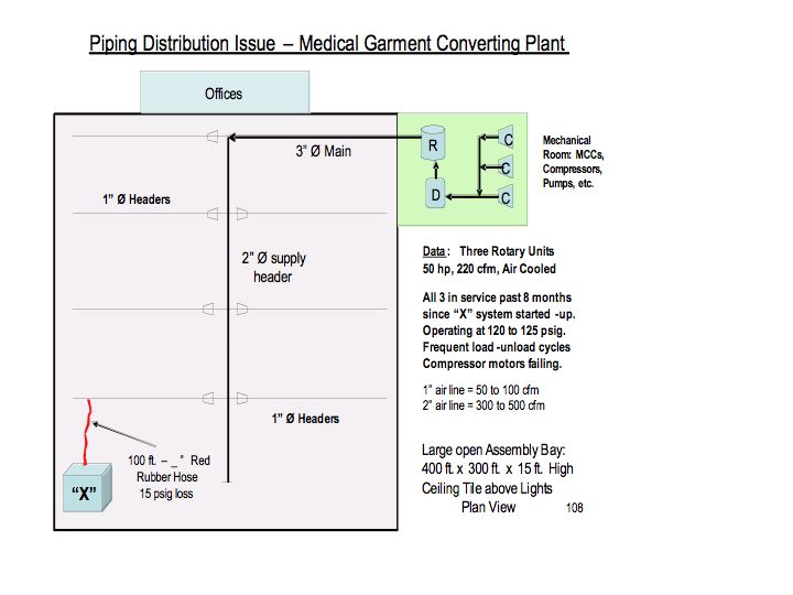
3. A healthcare garment plant in the Southwest added a new, large, automatic packaging machine at the rear its converting area. All three of its 50 hp rotary compressors were operating at 125 psig (and burning up motors). Previously, two units supplied the plant at 95–100 psig. Inspection identified 100' of ½" rubber hose supplying air to the new machine from the nearest 1" air line. A new ¾" copper line was run to the 2" main header, and the plant returned to operating two compressors at 100 psig.
4. A three-story research facility had recently installed two new development machines on the first floor. Air pressure had to be increased to 125 psig at the two 25 hp reciprocating units in the fourth floor mechanical room. The compressors were cycling ‘on-off’ continuously at two-minute intervals and motor failures had occurred. The 300' long, ½" copper air line running down and through the first floor equipment hallway was determined to be the issue. A second air line (¾" size) was installed to the new machines.
5. Two large 90,000 cfm pulsejet baghouses at a bronze foundry were pulse cycling continuously and bag failure rate was excessively high. We identified a ½" air line supplying the air manifold atop each baghouse structure. Air supply couplings on the manifold (provided by the vendor) were 1" size. Testing revealed air pressure drop during each pulse cycle down to 40 psig, recovering only to 75–80 psig for the next cycle. Replacing the 100' long, ½" lines with 1" size solved the problem.
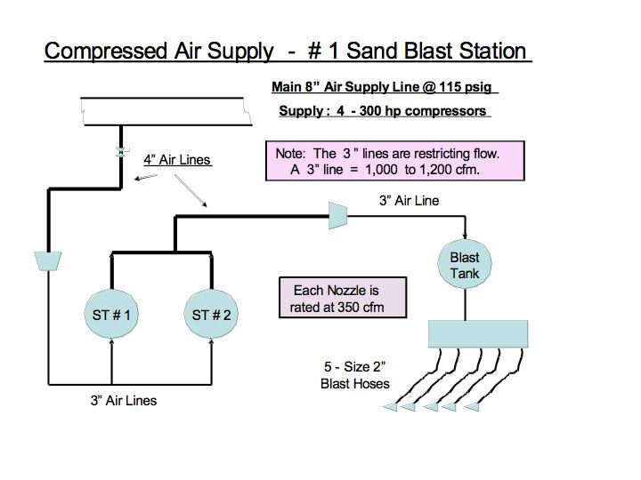
6. Two new sandblasting units were added to an existing three-unit station (to speed up the painting line) at a tank-car fabrication plant. Four 300 hp rotary units supplying the huge building were operating at 115–118 psig. Investigation identified 3" air lines to the local surge tanks and blast mix tank. Five sandblast units required 1,750 cfm of air at 90 psig. The 3" line was good for nominally 1,200–1,400 cfm. Replacing the 3" sections with new 4" pipe from the 8" main header improved blast gun performance and permitted a 10 psig lower compressor pressure.
7. Two 50 hp rotary compressors in a pharmaceutical plant packaging bay were operating at 115–120 psig, despite the 3" main air lines in the building and 80 psig pressure specification for the machines. Air line ‘drops’ to the six machines from the 3" main in the ceiling were 40' long, ½" size hydraulic hose. The HSE manager explained that hydraulic hose was used for employee safety reasons. New, ¾" copper pipe ‘drops’ solved the problem. The compressors now operate at 90–95 psig.
8. A dual-tower regenerative air dryer in the boiler plant of a paper mill was incurring a 25 psig pressure drop. Mill personnel had raised the air pressure to 110–115 psig at the two 300 hp rotary compressors to compensate. Marginally sized, 3" air header piping at the dryer towers and fouled dryer media (due to unfiltered air supplying the regenerative blower) were identified as the problem.
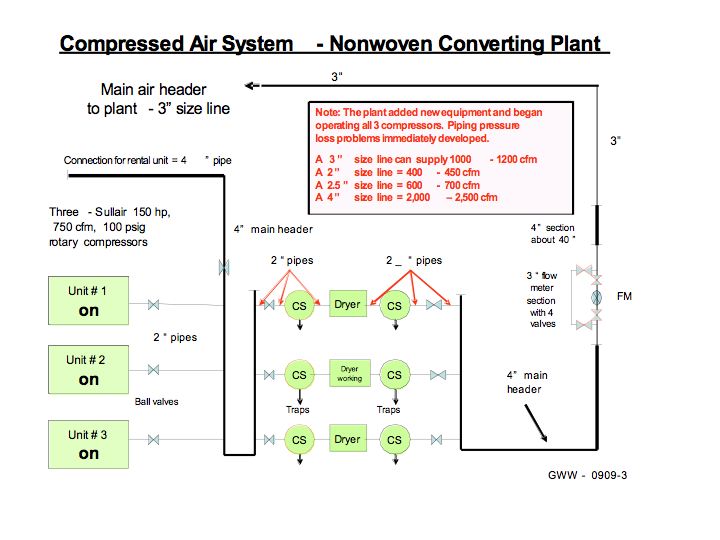
9. A nonwovens plant in Northern Mexico installed a new production line that increased air demand by 30%. Since capital funds for the project were tight, the project engineering team decided to use the plant ‘stand-by’ compressor. At start up, the three 150 hp units were operating at 120 psig, yet pressure in the plant was inadequate. The engineering team had failed to recognize that the original piping system was designed for a ‘two-compressor’ operation. Several piping changes at the compressors and a new 2" supply line to the expansion area were needed.
Summary and Recommendations:
If your plant operates air compressors above 95–100 psig, you should know why, and have a sound technical reason for that condition. The higher the system air pressure, the greater the leakage. Not only energy cost savings, but also long-term reliability of the compressors will result when operating at 90–100 psig versus units operating continually at 115–125 psig. Most process equipment should operate reliably with 80 psig air supply to the machine manifold (with some specific exceptions such as large air cylinders, pulse-jet baghouses and sandblast units).
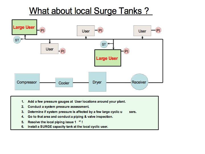
A technical assessment of the piping distribution system and identifying high ‘point-source’ surge demand conditions should be the first order of business if low air pressure in manufacturing is a major issue. Repairing air leaks and installing additional compressors and expensive controls will not rectify a basic pipe distribution system or process machine operational issue. Having too many compressors in service, needing equipment maintenance work, upgrading controls and repairing large leaks certainly are issues that need to be addressed. However, do not allow improperly sized air piping and fittings at one or two process machines in your plant to dictate a higher pressure for the entire system. Be sure that your Compressed Air System Assessment Team flies their ‘helicopter’ far enough above the trees to see all of the forest.
For more information, please contact Mr. Gary Wamsley, PE, CEM, JoGar Energy Services, Tel: 678-977-1508, or visi www.jogarenergy.com.