
Condensate drains are possibly the least glamorous and most ignored component of a compressed air system but nevertheless, a most important part. No matter how much you spend on that fancy new compressed air system, VFD’S pin-stripes and flashing lights notwithstanding, not spending a little effort with your drain choice could cause you no end of headaches and increased operating costs for years to come.
Contaminants can enter a system at the compressor intake or be introduced into the airstream by the system itself. Lubricant, metal particles, rust, and pipe scale are all separated and filtered out, but it’s the drains that have to operate properly for the filters and separators to be successful in completing their task.
Drains can be found on an intercooler, aftercooler, filter, dryer, receiver, drip leg, or at point of use. Drains come in many types and variants for all these applications, some quote fancy, but they fall into these basic categories. No air waste – timer operated – open tube – none (yes that is a drain choice).
How do your drains improve system efficiency? Besides the obvious savings of compressed air with a no-waste drain choice, there are other less obvious ways drains can save energy or cost you energy if not properly maintained. They are key components in the quest for system efficiency and reliability.
When a drain fails to eject all of the condensate collected, oil and/or water will collect, affecting -- filter efficiency – causing carry over into the system – allowing freeze-up in the winter. On multiple stage compressors moisture carry over from the intercooler may allow liquid into the next stage causing premature wear and possibly a catastrophic failure. On your refrigerated dryer the temperature indicator may still read 38F, but if your drain has failed you’ll have plenty of water downstream. Slugs of water due to drain failure can cause major problems in a desiccant dryer. Drains stuck in the open position can be a major source of wasted energy in some plants.
Drain Types
No drain. Whether you choose to not install a drain, not repair a failed drain, or install a manual drain, the outcome is the same and falls into this category.
We see this all the time. Think about it. You purchase a filter for a reason. If it is only to collect dry contaminants (a desiccant dryer after filter or carbon adsorber for instance) then not having an automatic drain may be acceptable, but if there is the reasonable expectation of any liquid collecting, then why don’t you allow for that liquid to be ejected? Done manually on every shift change you say? Very doubtful, and besides, the amount collected can change with load and season and needs to be ejected at irregular times.

Figure 1: Manual valves left open waste huge amounts of energy.
An additional problem with the “no drain choice” is pressure drop. If your filter really isn’t working because everything it collects is carried over, why do you have it at all? You are only adding pressure drop and as we know, in a 100 psi system, every 2psi at the compressor requires 1% energy. Either install a drain so the filter works as designed, or remove the filter, then readjust your system controls accordingly to take advantage of the lower pressure drop.
Open tube. We find this “drain” in many places…..the solenoid drain that is stuck open and throttled back with a ball valve so it’s not quite so noisy…..the receiver with a very carefully adjusted ball valve…..the drip leg out on the factory floor, left open because “we used to have problems, and still do in the summer”…..the float valve that is stuck open because it cannot reseat itself.
Costs of use. Because so many factors have to be taken into account, this isn’t so easy to calculate, but anything up to 20 cfm continuous compressed air loss is common to find. More than that and I wouldn’t call this valve “cracked open”
Timer operated drain. These types of drains are a very popular option. Easy to install, cheap to purchase, and usually quite reliable if installed with a strainer on the inlet. Standard on many small refrigerated dryers, these drains come with an adjustable on-time and interval between drain events. Maintenance consists of pressing the “test” button to check its operation, making sure it is plugged in (quite often they are not!!) and cleaning the inlet strainer. A slightly different type of timer drain installed in larger systems is a motorized ball valve with timer.
As nice as this solution seems, except for some very special applications, timer operated drains should be considered a quick fix only. Problems include…..not opening long enough to eject all the condensate…..staying open too long wasting compressed air….., oil particles contained in the condensate can undergo change partly because of high velocities and direction changes, forming stable emulsions and causing problems with proper condensate separation and ejection.
It is recommended that the operator adjust the drain times to match the seasons, but just like the manual drain, we cannot rely on our operators taking care of this chore reliably and additionally we still have daily ambient conditions to contend with. Gone (hopefully) are the days of installing timer drains on each receiver, separator, pre-filter dryer, and after-filter, ending up with a wall full of drains, possibly all firing at once.
How much compressed air does a timer drain use?
For instance, a ¼” timer drain with a ¼” orifice and 100psi at the inlet will move approximately 108 cfm. However, they don’t have a perfect orifice, so we have to apply a coefficient, 60% would be reasonable (but this can be calculated out). Taking this into account, this drain now moves 108 x 60% = 64.8 cfm. If this drain were open for 10 seconds and off for 3 minutes. 64.8 x 10/180 = 3.6 cfm average flow. If you know how to calculate your compressed air cost then you are all set. If not, use \$180 per cfm as an average (\$0.10 per kWh) In this case we have the potential savings of \$648.00 per year, even more in the northeast where we pay \$0.15-20/kWh.
Other considerations that may affect this drain flow calculation are…..length and ID of inlet pipe to the drain…pressure at the orifice while moving air…orifice size…orifice coefficient…length and id of the discharge line to drain, and more.
Which leads us to the less obvious energy cost of timer drains…... like any other system demand, timer drains use air and that air has a cost. However, the firing of a drain (or two, or three) could cause enough of a pressure drop in the compressor room (or just in front of a compressor pressure transducer) to require an off-line compressor to start up. Now we have added electrical cost to run that compressor, as well as added maintenance (I’m sure this doesn’t happen just once) and a fluctuating downstream pressure.
No Waste drains. This is a big category. A no-waste drain is one which will eject the collected condensate without also blowing compressed air, but will also automatically keep up with changes in the system.
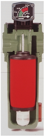
A float drain can be considered no-waste, in fact they can be considered a good choice for many filter applications. Filter bowl floats seem to be more reliable than they used to be. Today some come with a built-in particulate screen to prevent small particles from getting stuck under the seat, but maybe the use of cleaner piping becoming more prevalent (copper, aluminum) has helped this drain type’s reliability. As for maintenance, I would suggest replacing the float yearly, they really aren’t that expensive. Some filters come with an external float drain that could also be used elsewhere in the system. These can be mechanical floats, or small electronic drains, and all tend to be more reliable still. The mechanical floats include some very old designs that are great choices still today and can be rebuilt over and over.
The electronic choice comes in various sizes and works with a magnetic reed switch or capacitance device. The need of a power source can be a challenge, but these are commonly available with an alarm or alarm contacts. Rebuild kits are available for periodic maintenance, one manufacturer will have you swap out all “inards” as a module in one clean click.
 |
||||
Figure 2: Float drains should be repaced annually |
The last no-waste drain type is a hybrid of each of these drains. Available with a float mechanism that triggers (directly or via a magnet) either an electronic solenoid, closing before any air is lost, or the float triggers a pneumatic piston that opens a ball valve of some sort.
Although considered no-waste drains, these last types can in fact use a very small amount of air. Some install these models with a balance line that prevents air-lock but because we quite often find these closed off by Mr. Helper, a popular installation choice is to put in a small air bleeder instead. The pneumatic piston model also has the piston volume to account for. These are all extremely small “air leaks” but it is air use nonetheless.
Special Considerations
Make sure your drains are rated for the pressure you are running at.
On an oil-free system you may see more rust from a non coated receiver, and oil free air tends to be more acidic, so chose a drain with that in mind.
Many drain types are available with high level or unit failure alarms, as well as Teflon –type coatings, special materials of construction, even heating elements. Some even make drains for use on vacuum systems.
Top, side, bottom inlet are all available to fit most installations. Just make sure your installation doesn’t leave a liquid level in the vessel you are trying to keep clear. Some compressor manufacturers want their compressor elevated so the drains work properly.
Installation. It’s just a drain right? Who needs instructions? Well, quite often we find drains that were installed incorrectly.
Your drain might need a balance line from a specific pressure location, there may be special fittings included to prevent becoming air
 |
|
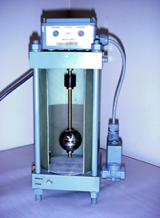
Figure 3: Float style external drain expels only condensate |
bound, strainers with service valves should be considered, drain leveling is always important.
Avoid connecting two drain points to one drain. There is likely to be different pressures at these two points and because air will take the path of least resistance, the lower pressure side will not get drained. In fact in a filter installation, you will have a direct path from the wet side of the first filter, totally bypassing the filter media and straight into the second filter or “dry” receiver.
On the factory floor, make sure you put a quality drain on any drip leg. That way you might prevent manufacturing personnel from opening up a valve just because that is what they have always done.
For more information contact the Compressed Air Challenge® at www.compressedairchallenge.org.
Ross Orr is presently a Sales Manager for Scales Industrial Technologies, one of the nations' leading air compressor distributors. He has worked for Scales in the sales and engineering department for over 20 years now. rorr@scalesair.com
Ross has experience with all types of air compressors and compressed air systems, vacuum systems, process cooling systems, energy management strategies, as well as complete system design and installation. In his time with Scales Air Compressor Corporation he has performed hundreds of walk-through evaluations and system assessments, as well as a number of full system audits. His experience has allowed him to show manufacturers significant energy savings and increased system quality and reliability.
To read more Technology articles, please click here.