Compressed air system controls match the compressed air supply with system demand and are one of the most important determinants of overall system energy efficiency. Proper control is essential to efficient system operation and high performance. “While there are other actions that impact on energy usage to produce compressed air, a properly applied and operating compressor capacity control system is the only way to translate less compressed air used into lower input electrical power and energy consumption.” advises Hank Van Ormer of Air Power USA, Inc, a senior compressed air auditor and an Advanced level CAC Instructor. The objective of any control strategy is also to shut off unneeded compressors or delay bringing on additional compressors until needed. All units that are operating should be run at full-load, except one unit for trimming.
Compressor systems are typically comprised of multiple compressors delivering air to a common plant air header. The combined capacity of these machines is generally sized to meet the maximum plant air demand. System controls are almost always needed to orchestrate a reduction in the output of the individual compressor(s) during times of lower demand. Compressed air systems are usually designed to operate within a fixed pressure range and to deliver a volume of air that varies with system demand. System pressure is monitored and the control system decreases compressor output when the pressure reaches a predetermined level. Compressor output is then increased again when the pressure drops to a lower predetermined level.
The difference between these two pressure levels is called the control range. Depending on air system demand, the control range can be anywhere from 2-20 psi. In the past, individual compressor controls and non-supervised multiple machine systems were slow and imprecise. This resulted in wide control ranges and large pressure swings. As a result of these large swings, individual compressor pressure control set points were established to maintain pressures higher than needed. This ensured that swings would not go below the minimum requirements for the system. Today, faster and more accurate microprocessor-based system controls and variable speed compressors with tighter control ranges allow for lower system pressure set points. Precise control systems are able to maintain lower average pressure without going below minimum system requirements.
A rule of thumb for systems in the 100 psig range is for every 2 psi increase in discharge pressure, energy consumption will increase by approximately 1 percent at full output flow (check performance curves for centrifugal and two-stage lubricant injected rotary screw compressors). There is also another penalty for higher-than-needed pressure. Raising the compressor discharge pressure increases the demand of every unregulated usage, including leaks, open blowing, etc. Although it varies by plant, unregulated usage is commonly as high as 30-50 percent of air demand. For systems in the 100 psig range with 30-50 percent unregulated usage, a 2 psi increase in header pressure will increase energy consumption by about another 0.6-1.0 percent because of the additional unregulated air being consumed. The combined effect results in a total increase in energy consumption of about 1.6 to 2 percent for every 2 psi increase in discharge pressure for a system in the 100 psig range with 30-50 percent unregulated usage.
Caution needs to be taken when lowering average system header pressure because large, sudden changes in demand can cause the pressure to drop below minimum requirements, which can lead to improper functioning of equipment. With careful matching of system controls and storage capacity, these problems can be avoided.
Controls and System Performance
Few air systems operate at full-load all of the time. Part-load performance is therefore critical, and is primarily influenced by compressor type and control strategy. The type of control specified for a given system is largely determined by the type of compressor being used and the facility's demand profile. If a system has a single compressor with a very steady demand, a simple compressor control system may be adequate. On the other hand, a complex system with multiple compressors, varying demand, and many types of end-uses will require a more sophisticated strategy. In any case, careful consideration should be given to both compressor and system control selection because they can be the most important factors affecting system performance and efficiency.
IoT and Compressed Air Management Systems – Webinar RecordingDownload the slides and watch the recording of the FREE webcast to learn:
|
Individual Compressor Control Strategies
Over the years, compressor manufacturers have developed a number of different types of control strategies. Controls such as start/stop and load/unload respond to reductions in air demand, increasing compressor discharge pressure by turning the compressor off or unloading it so that it does not deliver air for periods of time. Modulating inlet and multi-step controls allow the compressor to operate at part-load and deliver a reduced amount of air during periods of reduced demand.
Start/Stop. Start/stop is the simplest control available and can be applied to either reciprocating or rotary screw compressors. The motor driving the compressor is turned on or off in response to the discharge pressure of the machine. Typically, a simple pressure switch provides the motor start/stop signal. This type of control should not be used in an application that has frequent cycling because repeated starts will cause the motor to overheat and other compressor components to require more frequent maintenance. This control scheme is typically only used for applications with very low duty cycles for compressors in the 25 hp and under range. Its advantage is that power is used only while the compressor is running, but this is off-set by having to compress to a higher receiver pressure to allow air to be drawn from the receiver while the compressor is stopped.
Load/Unload. Load/unload control, also known as constant speed control, allows the motor to run continuously, but unloads the compressor when the discharge pressure is adequate. Compressor manufacturers use different strategies for unloading a compressor, but in most cases, an unloaded rotary screw compressor will consume 15-35 percent of full-load horsepower while delivering no useful work. As a result, some load/unload control schemes can be inefficient.
Modulating Controls. Modulating (throttling) inlet control allows the output of a compressor to be varied to meet flow requirements. Throttling is usually accomplished by closing the inlet valve, thereby restricting inlet air to the compressor. This control scheme is applied to centrifugal and lubricant-injected rotary screw compressors. This control method cannot be used on reciprocating or lubricant-free rotary screw compressor and when applied to lubricant-injected rotary screw compressors, is an inefficient means of varying compressor output. When used on centrifugal compressors, more efficient results are obtained, particularly with the use of inlet guide vanes which direct the air in the same direction as the impeller rotation. However, the amount of capacity reduction is limited by the potential for surge and minimum throttling capacity.
Inlet valve modulation used on lubricant-injected rotary air compressors allows compressor capacity to be adjusted to match demand. A regulating valve senses system or discharge pressure over a prescribed range (usually about 10 psi) and sends a proportional pressure to operate the inlet valve. Closing (or throttling) the inlet valve causes a pressure drop across it, reducing the inlet pressure at the compressor and, hence, the mass flow of air. Since the pressure at the compressor inlet is reduced while discharge pressure is rising slightly, the compression ratios are increased so that energy savings are somewhat limited. Inlet valve modulation normally is limited to the range from 100 percent to about 40 percent of rated capacity, at which point the discharge pressure will have reached full load pressure plus 10 psi and it is assumed that demand is insufficient to require continued air discharge to the system. At this point the compressor can fully unload as previously described in a compressor using load/unload control.
Dual Control/Auto Dual. For small reciprocating compressors, dual control allows the selection of either Start/Stop or Load/Unload. For lubricant-injected rotary screw compressors, auto dual control provides modulation to a pre-set reduced capacity followed by unloading with the addition of an over-run timer to stop the compressor after running unloaded for a pre-set time.
Variable Displacement. Some compressors are designed to operate in two or more partially-loaded conditions. With such a control scheme, output pressure can be closely controlled without requiring the compressor to start/stop or load/unload.
Reciprocating compressors are designed as two-step (start/stop or load/unload), three-step (0%, 50%, 100%) or five-step (0%, 25%, 50%, 75%, 100 %) control. These control schemes generally exhibit an almost direct relationship between motor power consumption and loaded capacity.
Some lubricant-injected rotary screw compressors can vary their compression volumes (ratio) using sliding or turn valves. These are generally applied in conjunction with modulating inlet valves to provide more accurate pressure control with improved part-load efficiency.
Variable Speed Drives. Variable speed is accepted as an efficient means of rotary compressor capacity control, using integrated variable frequency ac or switched reluctance dc drives. Compressor discharge pressure can be held to within +/- 1 psi over a wide range of capacity, allowing additional system energy savings.
Rotary screw compressors with fixed-speed drives can only be stopped and started a certain number of times within a given time frame. Depending on the control scheme used, instead of stopping the compressor, it will be unloaded, throttled, or the compressor displacement will be varied in applications where the demand for air changes over time. In some cases, these control methodologies can be an inefficient way to vary compressor output. Compressors equipped with variable speed drive controls continuously adjust the drive motor speed to match variable demand requirements.
In a positive displacement rotary compressor the displacement is directly proportional to the rotational speed of the input shaft of the air end. However, it is important to note that with constant discharge pressure, if efficiency remained constant over the speed range, the input torque requirement would remain constant, unlike the requirement of dynamic compressors, fans or pumps. The actual efficiency also may fall at lower speeds, requiring an increase in torque. Electric motors and controllers currently are available to satisfy these needs, but their efficiency and power factor at reduced speeds must be taken into consideration.
Air Compressor Technology Monthly e-NewsletterWith a focus on Supply-Side Optimization, air compressor technologies and compressor control systems are profiled. System Assessment articles detail what compressor controls allow kWh consumption to match system demand. |
Multiple Compressor Control
Systems with multiple compressors use more sophisticated controls to orchestrate compressor operation and air delivery to the system. Network controls use the on-board compressor controls' microprocessors linked together to form a chain of communication that makes decisions to stop/start, load/unload, modulate, vary displacement, and vary speed. Usually, one compressor assumes the lead role with the others being subordinate to the commands from this compressor. System master controls coordinate all of the functions necessary to optimize compressed air as a utility. System master controls have many functional capabilities, including the ability to monitor and control all components in the system, as well as trending data to enhance maintenance functions and minimize costs of operation. Other system controllers, such as pressure/flow controllers, can also substantially improve the performance of some systems.
Network Controls. Network controls use the on-board compressor controls' microprocessors linked together to form a chain of communication that makes decisions to stop/start, load/unload, modulate, vary displacement, and vary speed. Usually, one compressor assumes the lead role with the others being subordinate to the commands from this compressor.
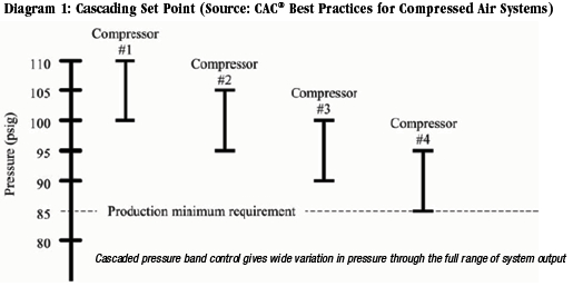
Less sophisticated network controls use the cascade set point scheme to operate the system as a whole. Those systems are capable of avoiding part load compressors but can still present the problem of approaching production's minimum pressure requirement as more and more compressors are added and the range of compressor load and unload set points increases.

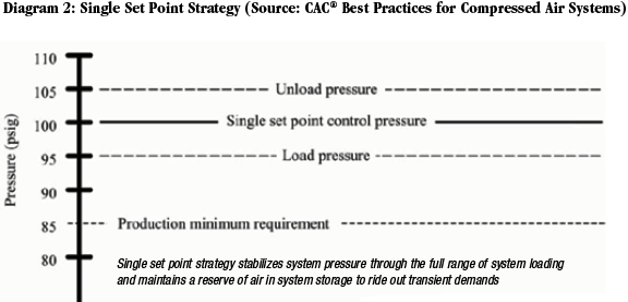
The more sophisticated network control systems use single set point logic to make their operational decisions to start/stop, etc. In systems with positive displacement compressors (reciprocating, rotary screws, etc.) all compressors are kept fully loaded except for one compressor that is operated in some part load fashion specific to the design of the machine.
Three major disadvantages of network system controls are:
• They are capable of controlling only air compressors,
• They cannot be networked with remote compressor rooms without a master control of some type, and
• Typically they only work with compressors of the same brand and configuration because of microprocessor compatibility issues.

Expensive upgrades or retrofits may need to be made to make different brands of compressors or older versions of the same brand work in the system. In some cases retrofits are not available and different brand or outdated compressors cannot be used in the control scheme.
There are no network controls available that can coordinate the control of rotary screw, reciprocating, and centrifugal compressors as one system. To do this, system master controls are required, especially if there is a desire to monitor and operate compressors, cooling systems, dryers, filters, traps, storage, pressure/flow controllers, and any other part of a compressed air system that a facility might want included in the control scheme.
System Master Controls. If complexity outpaces the capabilities of local and network controls, a system master control is required to coordinate all of the functions necessary to optimize compressed air as a utility. System master controls have many functional capabilities, including the ability to monitor and control all components in the system, as well as trending data to enhance maintenance functions and minimize costs of operation. System master controls interface with all brands and types of air compressors, and can coordinate the operation of satellite compressor rooms spread around the facility, or in different buildings across an industrial campus. The primary function of these controls, as with the network controls, is to operate a multiple compressor system in harmony. “Pressure actuated central capacity control systems are basically reactive in nature meaning, regardless of a response time, no action can be taken until after something has occurred.” Says Van Ormer, “There is a trend in recently developed central air management systems of using system pressure combined with flow based data to create more proactive systems. Combining many critical data inputs into the software analysis such as unit load position, specific power and, particularly with mass flow compressors, ambient and inlet conditions, often allows a timely adjustment prior to the actual event optimizing the system even more. There are many action data inputs used. See article Compressed Air Management Systems, Compressed Air Best Practices Magazine, October 2009.”
The least sophisticated have few if any of the features mentioned above and use cascading set point logic to control compressors. The most sophisticated, state-of-the-art system master controls use single point control logic with rate of change dynamic analysis to make decisions regarding how the compressed air system responds to changes. These changes can occur on the demand side, supply side, or in the ambient conditions - all affect the performance of the system and have a role in how the system should respond. Some of these require short duration support, such as additional storage.
Multiple Compressor Control with VSD
Control of multiple compressors in a system that includes fixed speed and VSD compressors requires special a special approach to avoid unintended system and control issues. This subject is beyond the scope of this article and planned for a future CAC submission. If this situation applies to you, or you are interested in applying a new VSD compressor to your system, we recommend reading a further discussion of Multiple Compressor Controls that appears in CAC’s “Best Practices for Compressed Air Systems” Appendix 2.A.4 (This 325 page manual is available at the CAC bookstore). To purchase your copy go to our Compressed Air Challenge® website.
To read more Air Compressor Technology articles, please visit www.airbestpractices.com/technology/air-compressors.


