
A retrofit replacing continuous pneumatic vacuum holding with spring-return magnetic grippers delivers lower energy consumption, reduced maintenance and a payback of less than one year
Compressed air is one of the most expensive utilities in a manufacturing plant, yet it is also one of the easiest to misuse. It’s often referred to as the fourth utility, alongside electricity, gas and water. It’s a clean, flexible utility well understood by maintenance teams and already distributed across most production areas. Those benefits are exactly why compressed air often becomes the default answer for every gripping, lifting, blowing, clamping and control function. For a plant manager or engineer who has lived through launches, model changes, weekend maintenance windows and Monday morning pressure complaints, the question is not whether or not compressed air has value. The question is whether or not a specific end use deserves to consume compressed air continuously when a mechanical or electromechanical alternative can do the same job with less risk, maintenance and energy.
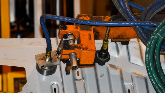
This article focuses on a project to replace vacuum cups with spring-return magnetic pickups for handling ferrous metal parts at an automobile assembly plant in Missouri. The application is most familiar in automotive stamping and body shop operations, but the lesson applies to any plant using vacuum cups to grab steel blanks, panels, brackets or formed parts. The original equipment in this case study used vacuum cups served by venturi devices. While a part was being held, the pneumatic vacuum system consumed compressed air. The retrofit replaced continuous pneumatic holding with magnetic pickups, using compressed air only for release. In other words, compressed air was moved from the holding function to the control function.
The distinction is important. A vacuum cup uses compressed air to create the useful force holding the part. A magnetic pickup uses magnetic force to hold the part and a small, regulated air pulse to break contact when the part must be released. That change may look small at the end effector, but it changes the load profile seen by the header, the compressed air dryer and the air compressor room. The project economics were compelling: A total installed cost of approximately $497 per magnetic pickup, average annual savings of about $592 per pickup and a simple payback of 0.83 years. The measured plant-wide air reduction after the first implementation phase was 800 cfm, with 436 cfm attributed to the magnetic pickup conversion.
Start at the End Use, Not the Air Compressor Room
The engineering logic behind this retrofit follows an inside-out approach. Instead of starting with air compressor efficiency, controls, compressed air dryers or storage receivers, the evaluation starts at the manufacturing process. What is the part? What force is required to hold it? How long does the gripper hold the part? How many times per hour does the cycle repeat? Does compressed air create value during the full holding time or only during a short release event? These questions are closer to the press, robot and tooling than to the air compressor room, which is exactly why they are powerful.
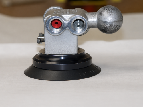
The baseline application used vacuum cups to grip metal parts on robotic or press-transfer tooling. The existing vacuum cup assembly included a venturi device. One red venturi uses a 0.04-inch orifice. Manufacturer data indicated air consumption of 1.6 scfm at 60 psig (4.1 barg) and estimated at 2.52 scfm at 90 psig (6.2 barg). A larger blue venturi with a 0.078-inch orifice uses 6 scfm at 60 psig (4.1 barg) and is estimated at 9.18 scfm at 90 psig (6.2 barg).
For plant personnel, the exact venturi color is less important than the operating behavior. The vacuum cup was effectively on while holding the part, and it operated at full line pressure. That means compressed air consumption was tied to holding time, not just to the motion event. If the part is held during a transfer, wait state, hesitation, production interruption or dry cycle, the end effector continues to consume air. In a plant where compressed air is shared by many processes, this kind of load contributes to base demand and reduces the room available for real process peaks.
Vacuum cups also bring maintenance realities. Cups wear, harden, crack, deform and lose sealing effectiveness. Oil, dirt, part surface variation and misalignment can reduce holding reliability. A small leak at the cup can become a continuous compressed air demand at the venturi. Maintenance teams know these failures because they show up as dropped parts, nuisance faults, repeated cup replacements, inconsistent pickup, pressure complaints or operators increasing air pressure to overcome a mechanical issue. Energy waste is often the accounting symptom of a reliability problem production already understands.
The Retrofit: Magnetic Holding, Pneumatic Release
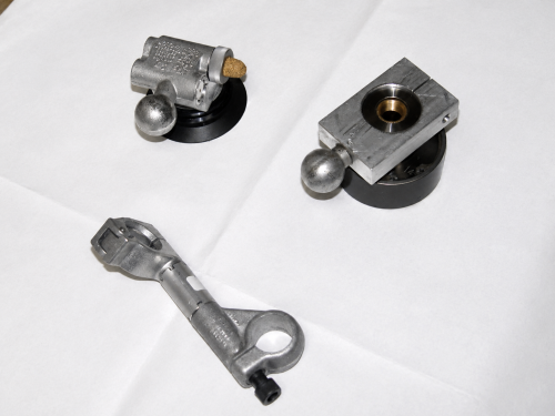
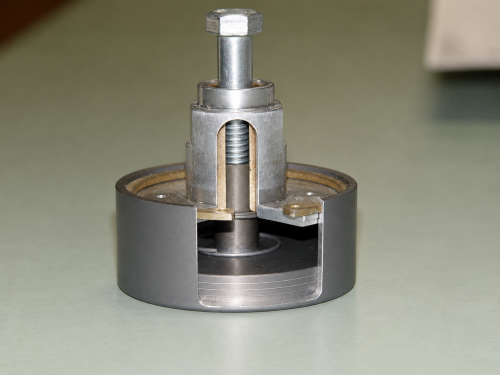
The replacement was a spring-return magnetic pickup designed for ferrous metal handling. The magnetic pickup held the part mechanically through magnetic attraction. Compressed air was not required to maintain the holding force. Instead, compressed air was supplied only when the part needed to be released. During release, compressed air entered the pickup through a small inlet port, pushed the internal magnet plates against a spring and created an air gap between the magnet face and the metal part. Once the gap was created, the magnetic holding force dropped enough for the part to release. When air was vented through small equalization openings, the spring returned the magnet plates to the holding position.
This control sequence is the core of the savings. The old system consumed compressed air while holding the part. The new system consumed a small amount of compressed air during blow-off. The magnetic pickup release air was approximately 0.29 cfm, with the release circuit regulated to 25 psig (1.7 barg).
A plant should resist the temptation to think of this as a simple component substitution. The better framing is functional substitution. The function is holding a ferrous part securely through a defined motion profile and releasing it cleanly at the right time. A vacuum cup accomplishes that function by continuously converting compressed air into suction. The magnetic pickup accomplishes the holding function without continuous air and uses compressed air only to create a release gap. Once that is understood, this project becomes easier to evaluate: Part material, part geometry, motion forces, face contact, release timing, residual magnetism and tooling adjustment become the key engineering questions.
Mechanical Integration: Reuse What Works, Replace What Wastes
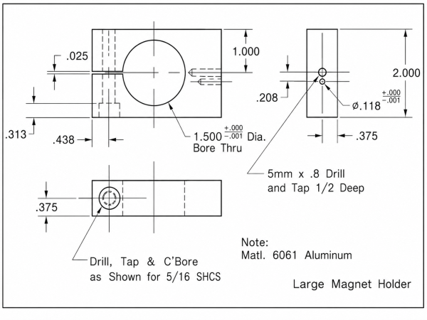
One reason this project was practical was it didn’t require a full redesign of the end effector. Existing adaptive tooling was reused in retrofit applications where the geometry allowed it. New adaptive tooling was manufactured from 6061 aluminum, using a 1 1/8-inch ball interface and a holder arrangement connecting the magnetic pickup to the existing tool structure. This simple conversion, requiring minimal reprogramming or mechanical adjustment, makes the opportunity more attractive. That matters because the largest barrier in a production plant is rarely the cost of a single component. It’s the risk of disrupting production, increasing cycle time or creating an adjustment problem maintenance inherits.
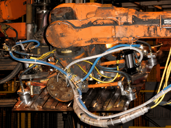
A magnetic pickup is not a universal replacement for every vacuum cup. It’s appropriate where the handled part is ferrous, where the contact surface supports reliable pickup and where release can be controlled without affecting part placement or quality. Plants should evaluate part thickness, coatings, oil film, curvature, temperature, available flat contact area, part orientation, acceleration, deceleration and the consequences of a failed pickup. In some cases, one magnetic pickup can replace one vacuum cup. In other cases, one magnetic pickup can replace two or more vacuum cups. Figure 7 shows an example where four magnetic pickups replaced eight vacuum cups.
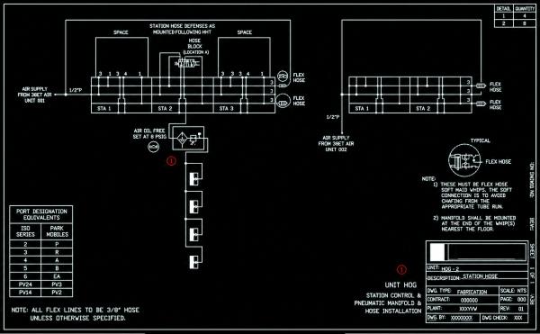
The air-side design is simple but important. The magnetic pickup release circuit used new piping, manifolds, hoses and fittings from a central filter and regulator to the magnetic pickups. The regulator reduced pressure to 25 psig (1.7 barg) for blow-off. A spring-return, single-position on/off pneumatic valve controlled the release event. Under normal holding conditions, the magnetic pickup didn’t need a continuous compressed air supply. During release, the valve passed regulated compressed air to the pickup long enough to create the air gap and let the part drop or transfer as intended.
The Economics: Small Hardware, Fast Payback
The material cost is $320 for each magnetic pickup, $32.50 for manufactured adaptive tooling and $80 for miscellaneous hoses, fittings, filters and pressure regulators. Labor was estimated at one man-hour per pickup at $63.42. The total installed cost was therefore $497 per magnetic pickup. The total includes the component, bracket, air-side accessories and labor to install the retrofit. It’s not a catalog price.
The savings estimate was built around the number of vacuum cups replaced. If one magnetic pickup replaced two vacuum cups, the annual energy cost savings were $790. If one magnetic pickup replaced one vacuum cup, the annual savings were $395. Taking the average of those two cases produced an expected savings value of $592 per magnetic pickup. Dividing the $497 installed cost by $592 per year produced a simple payback of 0.83 years. In practical plant language, that’s a maintenance-friendly project paying back in less than a year while reducing a continuous pneumatic load.
The economics become more interesting when the project is scaled. A single pickup may not move the plant utility bill, but a body shop zone, transfer line or press line can. The first implementation phase attributed 436 cfm of compressed air reduction to the magnetic pickup conversion. At that level, the savings are no longer a theoretical calculation per cup. They are visible on the plant air chart. For a plant manager, that’s the difference between an energy idea and a production utility improvement.
Measurement and Verification: Trust the Trend, but Know Its Limits
Measurement and verification for compressed air projects are rarely perfect in a real plant. Department-level air meters may be missing, inaccurate, out of calibration or located in a way that mixes multiple project effects. The team acknowledged plant-wide air tracking was the most practical method available because department air flow metering was not sufficiently accurate. That’s a useful lesson. Don’t let imperfect metering stop a good project, but don’t pretend the metering is better than it is. State the boundary, explain the method and compare the results to production conditions.
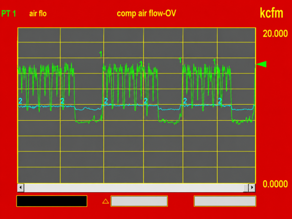
The plant-wide compressed air chart shows a reduction from 16,000 cfm to 15,200 cfm after the first implementation phase. The total achieved compressed air savings were calculated as 800 cfm. Of that reduction, 436 cfm was attributed to the magnetic pickup conversion. For an experienced engineer, the right response isn’t blind acceptance or automatic rejection. The right response is asking what else changed, if production volume was comparable, if pressure settings were stable, if air compressor operation changed, if other projects were implemented and how the attribution was developed. That is how compressed air savings should be discussed with operations.
Even with those caveats, the result is meaningful. A several hundred cfm end-use reduction is large enough to affect air compressor staging decisions, especially during lower-load periods. It can reduce blow-off on centrifugal air compressors, reduce compressed air dryer load, lower heat rejection and create room for maintenance flexibility. The best measurement and verification practice is combining component-level engineering estimates with plant-level compressed air demand trending. The estimate tells you what the retrofit should save; the trend tells you whether or not the plant actually saw a reduction. When both point in the same direction, the project becomes credible.
What Can Go Wrong and How to Prevent It
The most common mistake is treating the retrofit as only an energy project. The production team will support the project when it improves or protects reliability. They’ll resist it if it appears to trade production confidence for utility savings. The project team should therefore bring production, maintenance, controls, safety and energy personnel into the same review. The discussion should cover part-hold force, release confidence, robot motion, emergency stops, lockout behavior, adjustment methods, spare parts, PM tasks and operator response to faults.
Another risk is assuming every vacuum cup should be replaced. Some cups handle non-ferrous parts, plastic, glass, fabric, painted surfaces or geometries where vacuum is still the correct tool. Some applications need compliance a rigid magnetic pickup may not provide. Some parts may be susceptible to marking, residual magnetism or release variation. A good plant standard should classify candidate applications rather than force a universal rule. Ferrous metal parts with repeatable contact surfaces, high vacuum holding hours and frequent cup maintenance are strong candidates. Marginal contact, sensitive surfaces, non-magnetic material and high release precision requirements need deeper testing.
How to Replicate the Project in Another Plant
Replication begins with a survey of vacuum cup applications touching ferrous metal parts. The survey should capture the number of cups, venturi type or orifice size, line pressure, operating hours, holding time, cycle count, maintenance history, part material and tooling constraints. The strongest candidates are usually not the most visible ones. They are the end uses consuming air continuously while holding, running during long production windows, requiring frequent cup replacement or remaining pressurized during idle periods. If local metering exists, trend the branch or cell before and after. If local metering is weak, use air compressor room flow data and document other changes.
The business case should be written in plant language. Discuss installed cost, air reduction, avoided maintenance, part-holding reliability and payback. Avoid overselling technology as a universal replacement. Present it as an engineered alternative for the right class of parts. A practical project screen might ask whether or not the part is ferrous, the contact surface is repeatable, the vacuum cup currently consumes compressed air while holding, one magnetic pickup can replace more than one cup, release can be controlled with a short, low-pressure compressed air pulse and the retrofit can be installed without major reprogramming. That’s the kind of screen a 30-year plant engineer will respect.
The Bigger Lesson: Lowering Demand-Side Use
The larger lesson from this case study is compressed air efficiency isn’t only an air compressor room discipline. It’s a production design discipline. The air compressor room responds to decisions made at hundreds of end uses. If those end uses require continuous air for functions that can be done mechanically, the most efficient air compressor in the world is still serving avoidable load. When a plant replaces continuous pneumatic vacuum holding with magnetic holding and a small release pulse, it removes demand at the source. That’s the cleanest form of compressed air savings.
Compressed air should still be used where it’s the right tool. It’s rugged, fast and deeply embedded in industrial operations. But it should not be allowed to hold steel parts all day when magnetic force can do the holding, and a short, regulated air pulse can handle release. The best plants will continue to challenge old assumptions. They’ll look beyond leaks, move upstream from the air compressor room and ask each end use a direct question: Are you using compressed air because you need it, or because nobody has asked a better question in years?
About the Author

Nasr Alkadi, Ph.D., CEM, CDSM, CSRM, is an energy and sustainability expert with over 20 years of experience in industrial energy management, compressed air systems, decarbonization, measurement and verification and strategic energy management. His work has included automotive manufacturing, the U.S. Department of Energy, national laboratory research, energy program delivery and practical implementation of energy efficiency projects connecting plant-floor reliability with measurable cost and emissions reduction. He’s authored or co-authored over 20 technical publications and is a named inventor on seven patents covering industrial energy analytics, remote inspection, sensing, emissions monitoring, air-fuel ratio regulation and related energy technologies.
About CLEAResult
CLEAResult is North America’s largest provider of energy efficiency, energy transition and energy sustainability services. Since 2003, its mission has been to change the way people use energy. Today, its experts lead the transition to a more sustainable, equitable and carbon-neutral future. Through hometown teams and a broad network of local partners, it delivers world-class technology and personalized services to help commercial and industrial businesses, governments, utilities and residential customers reduce energy use and greenhouse gas emissions. Headquartered in Austin, Texas, it employs nearly 3,000 people across over 60 cities in the U.S. and Canada, and is majority owned by U.S. middle market private equity firm Kohlberg.
CLEAResult is North America's largest provider of energy efficiency, energy transition and decarbonization solutions, helping utilities, businesses, governments and communities reduce energy use and improve program impact. For more information, visit https://www.clearesult.com.
To read articles on the Compressed Air End Uses, visit https://www.airbestpractices.com/system-assessments/end-uses.
For expert presentations, visit our Webinar Archive Section dedicated to Air Compressor Technology at https://www.airbestpractices.com/webinars.
