Introduction
Compressed Air Consultants performed a compressed air system audit at a commercial bakery. The primary objective of the audit was to determine the constituents of demand that have contributed to the increase in demand over the last couple of years. Presently the plant must operate all three available air compressors in order to support the full production needs of the plant. Therefore, there is insufficient backup to support full production in the event of a primary compressor failure.
The secondary objective of the audit is to determine what opportunities exist to reduce compressed air demand further so that less than two fully loaded compressors are able to support the needs of the plant during all shifts. The supply arrangement was analyzed to determine the integrity of the equipment with the intention to improve compressed air efficiency and quality. The header network was monitored in several locations to determine if any flow restrictions exist.
The current cost to operate the compressed air system is \$139,100 annually, and the proposed measures will reduce it by \$50,700 annually. The proposed cost to complete the measures is \$47,600 providing a simple payback of 11 months. The cost included in the Action Plan includes engineering, project assistance, services to maintain the gains, and a 10% contingency.
Brief Description of the Supply-Side
During full production, the plant is supported by three (3) available rotary screw air compressors located outdoors under the cover of a roof. The flow of compressed air from the compressors feeds a wet receiver tank located beside the compressors and then through 185 feet of 4” pipe to the compressed air dryer room located inside the main facility on a Mezzanine. The 4” wet header feeds a single 1,500 Scfm depth-of-bed mist eliminator and then to a 140-gallon wet receiver tank located on the mezzanine above the Fermentation Room.
Downstream of the tank is a single 1,250 Scfm cycling type refrigerated air dryer. A pressure control station is installed downstream of the dryer which regulates the air to a lower pressure before being delivered to the distribution header. A dry receiver tank is teed into the line upstream of the pressure control station to extend the cycling time of the air compressors and improve the pressure control of the station.
An oil water separator is located in the Main compressor room outside but such equipment is not present in the Mezzanine area where the dryer, small tank, and mist eliminator are located. The system is equipped with compressor automation coordinating the sequencing of the air compressors based on the prevailing system demand.
The compressed air audit was a full supply and demand-side system assessment. Due to article length limitations, this article will share the results of only the demand-side audit.
Constituents of Demand in the Bakery
The plant demand during full production (Bread, Roll, and Muffin Lines operating) when all lines were in operation is 974 Scfm (1st profile), and reduces to 816 Scfm when the Muffin line is shut down (2nd profile) The demand drops to 746 Scfm during the four hour cleaning cycle (3rd profile) which occurs every day.
Since the last compressed air audit, conducted over ten years ago, the Roll make-up area has been upgraded with new equipment that has changed the demand profile of the facility. There are other users that have been added to the system but which had not been identified before this audit.
Below is the distribution makeup of the compressed air usage for the facility. Note the largest area consumer of air in the plant resides in the Flour Room area. This anomaly is due to a malfunctioning dust collector that is discussed later in the report. The plant maintenance and engineering team has done a great job of maintaining high levels of production with minimal waste. An example is there are very few leaks representing less than 5% of the entire load (50 Scfm).
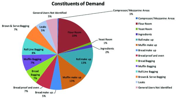
Click to enlarge.
Demand Side Projects to Enable Air Compressor Redundancy
The audit has identified over 300 Scfm of demand side reductions that will restore the system back to a point where the plant can operate on two air compressors during full production. Please note it is important that all measures are completed as it will enable the facility to withstand the loss of its largest compressor, a 125 HP unit, during the summer months without impacting production.
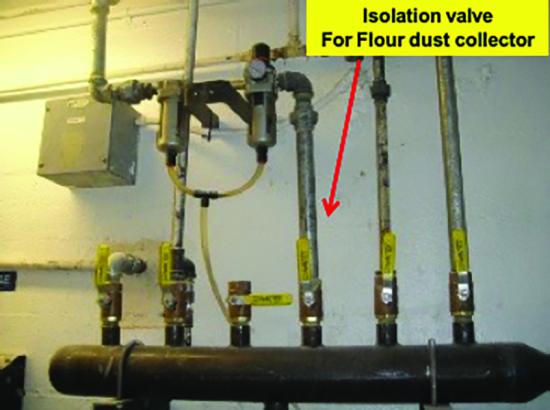
1. Flour Room: Flour Dust Collector on Roof
The pilot valve assembly on a ¾” solenoid valve on the Flour dust collector located on the roof has come disconnected allowing 175 Scfm of air to continuously blow. The supply of air and primary isolation valve for the Flour dust collector is located in the Flour Room. The malfunctioning pilot assembly valve is consuming 175 Scfm and represents 16% of the entire system demand. The malfunctioning solenoid valve is the primary reason the plant can no longer support full production with two (2) air compressors. During the study we shut off the supply of compressed air to the Flour dust collector during full production and noted that the reduction in demand enabled the third on line compressor to unload, time out, and shut off. This test confirmed the plant can in fact operate on two air compressors if the pilot solenoid valve on this dust collector is restored.
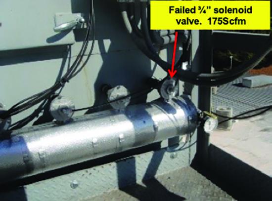
The primary cause of the failure is the connection fitting on the pilot air solenoid valve, which needs to be upgraded to a compression type fitting so that it does not occur in the future. The dust collector can also be retrofitted to operate on differential pressure instead of timer based to reduce the demand from 10 Scfm to 3 Scfm.
2. Bread Line Minor Ingredients Station
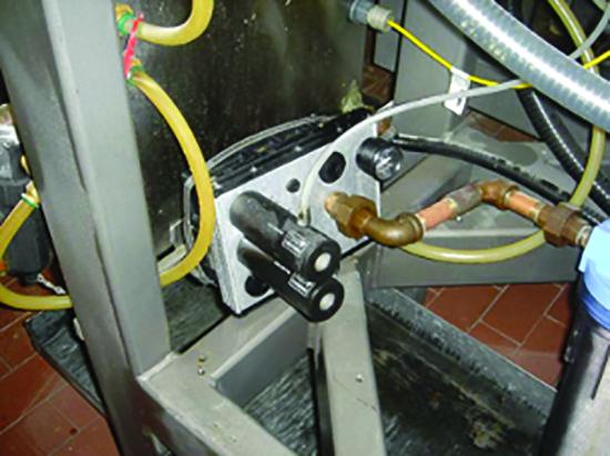
The Ingredients Station is equipped with a pulse regeneration dust collector. The dust collector cleans the filter bags that catch the airborne flour from the mixing process at the station. The dust collector is equipped with a controller that is set for a fixed regenerating pulse interval of three (3) seconds set for a pulse duration of 0.22 seconds. When the dust collector is in operation (in automatic mode), the dust collector consumes an average of 26 Scfm and can represent as much as 3% of the entire compressed air demand. We project that the station is in use about 50% of the time. Often the station is left idle for extended periods of time while the machine is not manually stopped causing the dust collector to continue to consume air for regeneration even though it is not needed. The existing controller on the dust collector can be retrofitted to accommodate a Photohelic for differential pressure control.
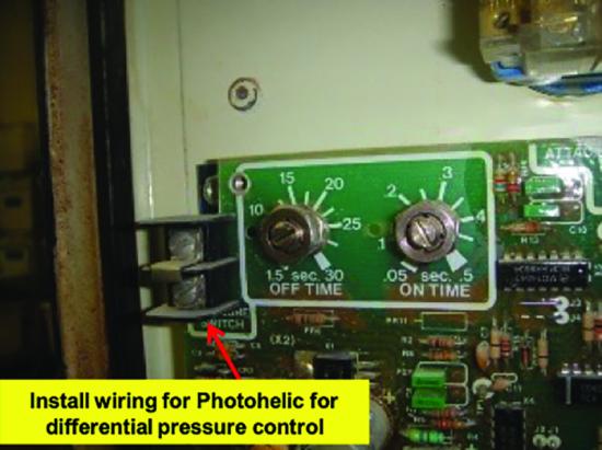
We propose installing a photohelic differential pressure control to the existing controller as shown in the picture. We project the plant can eliminate about 50% of the average demand or 6.5 Scfm by completing this measure. In the future, if the operator leaves the machine on and leaves the station, the dust collector will only pulse when the differential across its tube sheet reaches a certain level.
3. Air Knife on Pan Cleaner for Bread Line
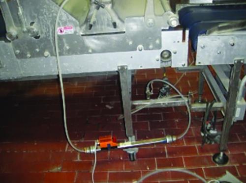
On the bread line an air knife is used cleaning the empty bread pans before being returned to the beginning of the line. During the study an inline flow meter was installed on this application and it was measured to consume an average of 37 Scfm. The supply of compressed air to the air knife is configured without a solenoid valve or a proximity switch for automatic operation and therefore consumes air continuously even if a pan is not present.
There are opportunities during production, where there is an interruption to the flow of bread pans returning to the Pan cleaner, where the supply of compressed air can be automatically turned off. There is an existing proximity switch upstream of the pan cleaner that can be utilized to detect the presence of a pan and in turn determine whether compressed air is required at the Pan Cleaner air knife. We project that air is not required 30% of the operating time for the Pan cleaner and will reduce the average compressed air demand by 12 Scfm. Install a solenoid valve on the supply of compressed air that is controlled using the existing proximity switch located upstream of the pan cleaner station.
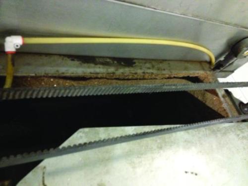
37 Scfm Continuously. Install Solenoid valve activated by existing proximity switch.
4. Secondary Pan Cleaner on the Bread Line
There is a secondary pan cleaner on the Bread line used intermittently for additional cleaning. The secondary pan cleaner is typically used when the small bread pans are used with toppings, which often leave product hard to dislodge. The air consumption of the secondary Bread Pan cleaner is 50 Scfm based on a measurement using a flow meter. The secondary pan cleaner uses a homemade air-knife consisting of twenty-six (26) small holes.
Using an engineered air knife in place of home-made drilled holes will help reduce the compressed air consumption. The difference in compressed air consumption is over 2:1 at the same inlet pressures. We project the air consumption of the secondary Bread pan cleaner will be 25 Scfm when in operation. The primary motive for implementing this action is to ensure that the backup compressor is not turned on to support this intermittent event. A solenoid valve should also be installed that shuts off the supply of compressed air when a pan in not present. A new proximity switch may be required in order to detect the pan upstream of the secondary pan cleaner.
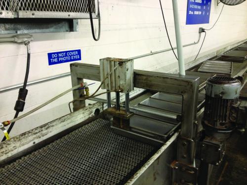
50 Scfm air consumption on homemade air knife used for small bread pans with toppings.
5. Open Blowing – Bag Tails
Open blowing is used for orienting the bag tails at the end of each line before being fed through the wrapper. By blowing air at high velocity between the pan and the bread, it frees the product from sticking. On all three lines, it is used to blow against the bag tail prior to adding the tie wrap. We observed that the compressed air usage in this area is not consistent as the consumption of each line for bag tails were 3, 6, and 8 Scfm for a total consumption of 17 Scfm.
A low-pressure blower can be used in this application but has not been received well when tested. If compressed air is continued to be used for this application, then a small flow meter should be installed on each application so that a standard can be established. We believe this application can be adequately served using 3 Scfm each. Establishing a standard for this application will reduce the average air consumption by 8 Scfm.
6. Open Blowing on Roll Line Flour Exhaust Hoods
Each of the two (2) roll lines is equipped with an exhaust hood for removing Flour from the Roll Pans using a vacuum system. The efficiency of the vacuum system is improved by the use of an air knife that tangentially deflects the flour off of the pan towards the exhaust hood. During the study an air flow meter was installed on the unit and it was determined that the average compressed air consumption per line is 27 Scfm for a collective usage of 54 Scfm for the two lines. The supply of compressed air to the exhaust hoods is continuous and cannot be shut off unless an operator manually shuts it off.
Each of the compressed air supply lines feeding the exhaust hoods should be retrofitted to automatically shut off if a Roll pan is not present on the line. A proximity switch will have to be installed upstream of the exhaust hood so that it can ensure air is being supplied to the exhaust hood as the pan cross under it. We project that 50% of the air for this application can be eliminated due to the running schedule. There is an opportunity to shut off the supply of air when there is an interruption to the product flow or when the line is down.
7. Farr Dust Collector for Roll Pan Cleaner
The Farr dust collector supporting the Roll Pan Cleaner operates on a continuous cleaning cycle. The pressure drop across the tube sheet of the dust collector is over 6” WC even when cleaning in a continuous mode. The interval between pulses for the dust collector is 15 seconds with a pulse duration of 0.15 milliseconds. The dust collector consumes an average of 5 Scfm. The filters in the dust collector need to be replaced and the unit switched to differential pressure control so that it only regenerates when the differential reaches a certain level. We project that there is a 3 Scfm savings by completing this measure.
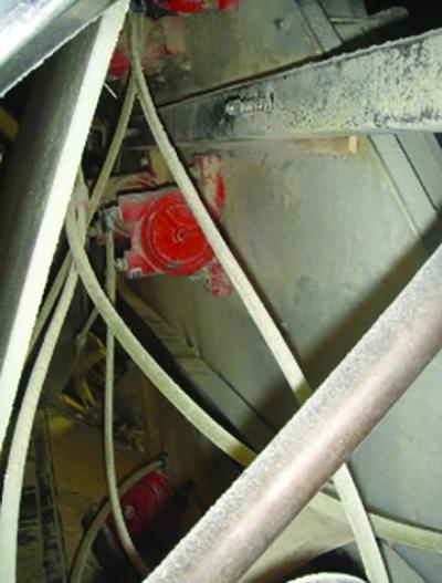
8. Muffin Line Air Vibrators
The facility uses a large amount of air vibrators to ensure the movement of the bread making ingredients. These devices perform their duties admirably; however, when considering the volume of air consumed which ranges from 7 to 30 Scfm each, do not out perform their electric counterparts. Understandably, the environment in which they are applied may force the facility to stay with the air vibrator due to the inability to run electricity to the vibrator or perhaps if the vibrator were in an explosive condition. Production has indicated that it is more difficult for the dough to freely travel down the line since corn meal is being used in lieu of flour.
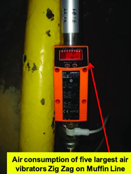
There are nine (9) air vibrators located downstream of the Muffin line dividers at the drop lines. The air vibrators are located on the Corn Meal feed chute, the sifter, on the drop section, and the Corn Meal reclaim system. During the study an in line flow meter was installed to measure the largest five (5) Vibco air vibrators. The five largest air vibrators consume 85 Scfm. Collectively, the nine (9) air vibrators on the Muffin Line consume 109 Scfm and represent close to 11% of the entire system demand. The plant has indicated that it is difficult to keep the product flowing in this area since corn meal is used in lieu of flour and the resistance or friction against the conveyor is much greater. They believe that the air vibrators do a satisfactory job keeping the Muffin dough flowing down the line.
On occasion we observed that the air vibrators continue to consume air even if the Muffin line is out of production unnecessarily taxing the compressor supply. The supply of compressed air is controlled using a manual isolation valve and therefore requires operator intervention in order to shut off the supply of compressed air during the appropriate times.
We propose installing an interlocked solenoid valve that shuts off the supply of compressed air when the line is out of operation. In addition, if the upstream conveyor to the line is idle, the air vibrators do not need to operate and can be automatically shut off with the new solenoid valve. We project that the Muffin line operates 50% of the operating hours during the week and the supply of compressed air is left on the air vibrators half of the time. Therefore, the consumption of compressed air for this application can be reduced by 25% by installing the interlocked solenoid valve. We project the average air consumption to be reduced by 22 Scfm (25% of 89 Scfm).
One of the air vibrators in this area is a large Vibco VS510 vibrator, located on the Corn Meal reclaim system cover directly below the drop area, consuming 20 scfm continuously. We propose replacing it with an electric vibrator which we believe will work satisfactorily for this specific application.
9. Vacuum Generators
There are five (5) engineered compressed air generated vacuum generators located at the Roll dough mixer, the Bread dough divider, muffin dough divider, and the Muffin and Brown & Serve box makers.These devices use compressed air to flow through the engineered passages within the device to create a vacuum for suction, and the compressed air is exhausted to atmosphere. The vacuum generators are consuming 10% (95 scfm) of the compressed air for the system.
With the exception of the box makers, the other four units were placed on the line to supplement an existing system that was not working properly. These devices work incredibly well, and their initial cost is inexpensive; however, the cost to generate the compressed air for these makes them a poor long-term solution. Based upon the cost to generate compressed air at this commercial bakery, using compressed air to generate vacuum versus a dedicated vacuum pump is four times less efficient. A dedicated vacuum system, however, for these operations would be difficult to justify due to the initial capital cost of the equipment, and the extensive piping network that would be required.
During the audit, the compressed air supplied to the vacuum generators on the bread dough divider and the roll mix would only energize when required, and would shut off when not in use. The air supply to the muffin divider, muffin box maker and Brown & Serve box maker are left on continuously, essentially acting as a leak. If the air supply were to be turned off to these vacuums when not in use, the plant demand would easily be reduced by 15 scfm assuming a reduction of usage by 50%. We propose installing similar controls be placed on the air supply for the Muffin and Brown & Serve vacuums as is used on the roll and bread units.
10. Empty Box Reject Station
There is an empty box reject station using compressed air to eject empty boxes that were not filled with brown and serve rolls. The open blowing application is a nozzle consuming 8 Scfm continuously. This application should be controlled using a solenoid valve where compressed air is only activated when the line is active. We project this measure can reduce the average air consumption of this application by 5 Scfm.
For more information about Compressed Air Consultants visit https://www.loweraircost.com/.
To read similar Food & Beverage Industry articles, please visit https://www.airbestpractices.com/industries/food.
Visit our Webinar Archives to listen to expert presentations on Compressed Air Purification, Pneumatics and Piping at https://www.airbestpractices.com/webinars.