According to the Compressed Air and Gas Institute (CAGI) and the International Organization for Standardization (ISO), the three major contaminants in compressed air are solid particles, water, and oil. CAGI promotes proper use of air compressors with various educational tools, while ISO 8573 is directed at the very specific areas of compressed air purity and test methods, which this article will address. Microorganisms are also considered a major contaminant by CAGI, but will not be discussed in this article.
ISO 8573 consists of nine parts or sections that address compressed air. ISO 8573-1 is the primary section that provides contaminants and purity classes. The other eight sections address sampling techniques and analytical methods for various contaminants. Each contaminant discussed will reference the appropriate ISO 8573 section, along with the current version date.
Particle Testing by Size per ISO 8573-4:2001
Particle testing is performed by size or by mass, depending on the selected purity class. Under ISO 8573-4:2001, this testing determines the number of solid particles within specified size ranges. Not all methods discussed in ISO 8573-4 can be used for all size ranges. Selection of a method will depend on the particle purity class required.
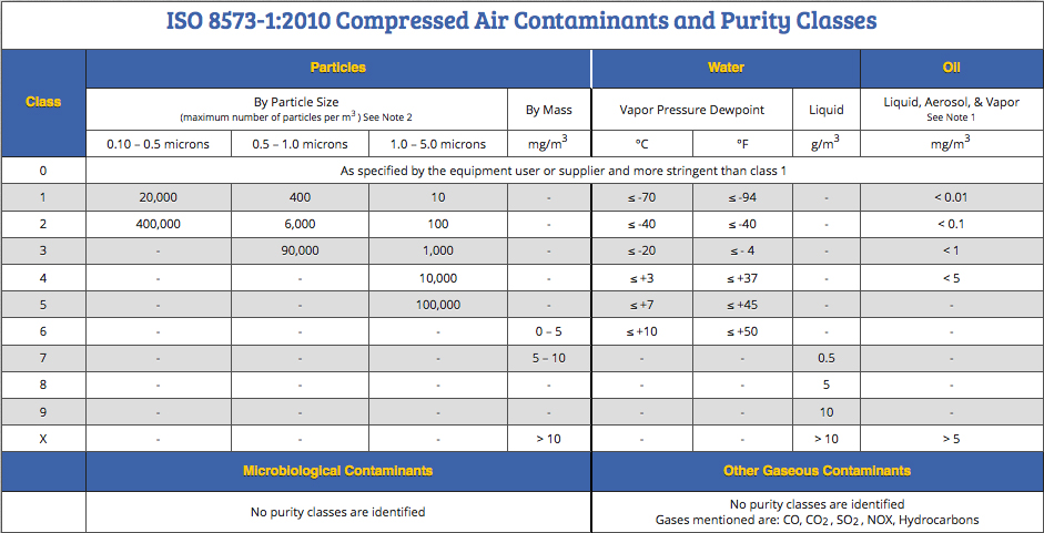
ISO 8573-1:2010 establishes three particle size ranges: 0.1 to 0.5 microns, 0.5 to 1.0 microns, and 1.0 to 5.0 microns. The maximum allowable number of particles per cubic meter varies by purity class. The specification does not allow the presence of particles greater than 5 microns for purity classes 1 through 5.
Click here to enlarge.
In the 2010 edition of ISO 8573-1, the particle size and maximum number of particles were harmonized with current filter manufacturer’s capabilities. This harmonization created an effective method to communicate requirements for a compressed air system between the end user, filter and compressor manufacturer, and testing laboratory.
Different Methodologies for Particle Testing
Laser Particle Counter: A laser particle counter (LPC) is a high-performance, sensitive electronic instrument, and it is an excellent method for determining all three particle size ranges for particle purity classes 1 and 2. The LPC provides rapid, on-site particle determinations. Operation is straightforward and typically takes about 10 minutes per sample. Many models have a printable tape and/or the ability to download the data to a computer or USB flash drive. While LPCs can be cost prohibitive if only a few samples are to be taken on an infrequent basis, they can be extremely helpful when a particle contamination problem exists. Not all LPCs include the ranges specified in ISO 8573-1.
Because the LPC can be used to sample multiple locations rapidly with on-site test results, it is an excellent troubleshooting device. We have had customers identify particle contamination sources as O-rings in valves and filter housings, flexible tubing, distribution piping, and plastic or metal fittings. In most cases, the contamination was not part of the sampling process but part of the actual manufacturing process.
Trace has a rental program that includes necessary calibration documentation, simplified sampling instructions, and a high-pressure diffuser to prevent damage to the sampler. Sampling procedures include a background test and tubing background test. This assures that the sampler is operating correctly prior to sampling compressed air outlets.
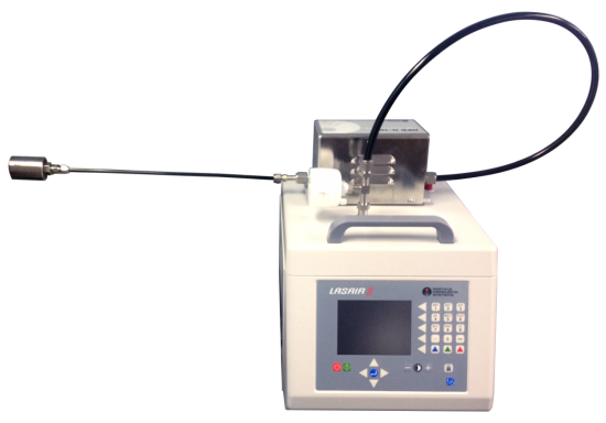
The LASAIR II-110, manufactured by Particle Measuring Systems, Inc., is a helpful tool when experiencing contamination problems. Photo credit: Trace Analytics, LLC
Filter Collection with Microscopy: Particles can also be sampled by using a gridded membrane in a suitable holder and analyzed using an optical microscope. Full flow sampling can be used with this type of sampling equipment. This method cannot measure the smallest range of particles, from 0.1 to 0.5 microns, for particle purity classes 1 and 2.
ISO 8573-4 describes a sampling probe that is inserted into a pipeline to capture a sample. To avoid the necessity of tapping into the actual pipe and performing the steps required to ensure isokinetic sampling (the matching of linear flow rates between the product and sample streams), Trace’s AirCheck™ Kit connects at the point of use, which allows for sampling the quality of compressed air in a manner that is representative of how it is being used in the manufacturing process.
Trace’s analytical method requires 12,000 liters of compressed air to meet class 1 requirements. Depending on the pressure and flow rate available at the sampling outlet, sampling may take two or more hours to collect. All other purity classes require 1,200 liters or less of air volume and only 12 minutes or less for sampling time.
Samples are analyzed using an optical microscope. This method is time and labor-intensive, but if performed by an accredited laboratory, the method provides customers with a third party, ISO 17025-accredited laboratory report. In some cases, useful information can be determined about the type of particles present. Samples are lightweight and easily transportable worldwide. Additionally, samples can be held indefinitely for re-analysis by microscopy or other more specific techniques.
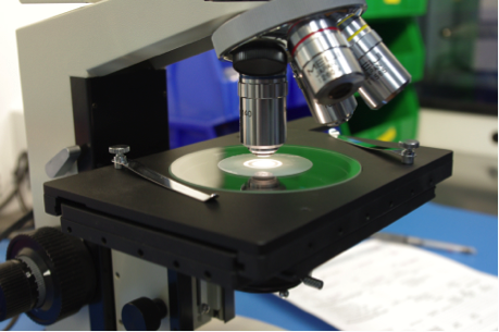
Microscopy is often used for particle determination. Photo Credit: Trace Analytics, LLC
There are other methods mentioned in ISO 8573-4 for particle determination that are not covered in this discussion. They include condensation nucleus counting, differential mobility analysis, and scanning mobility particle sizing. These techniques must generally be performed on site, and may be considerably more complicated than filter sampling. In addition, they may not provide results in terms that are readily converted to the units employed by the standard.
Solid Particle Content by Mass Concentration per ISO 8573-8:2004
Particle purity classes 6, 7, and X are typically used for industrial tools and pneumatically powered and operated machines with air filtered by general-purpose filters. Analyses for these classes specify mass concentration of particles by mass only. No particle size or quantity is determined. Results are reported in mg/m3.
The method for collecting the sample is similar to the membrane method, except that the weight of the membrane must be recorded prior to use and then re-weighed after collection of the sample. This gravimetric method of analysis must take into consideration the influence of temperature, pressure, water vapor and other contaminants that may be present.
Particle Sampling Tips for Compressed Air Systems
Whenever a sample is taken from a compressed air outlet, it is important to ensure that the sampling process itself does not contribute to contamination. The connection between the point of use and the sampling equipment should be short, straight, and made of stainless steel without elbows, tees, valves or dead ends. This enables easy cleaning in between multiple samples. The straight connection is important so as not to lose or trap particles before they are sampled.
Be aware that the use of quick disconnect fittings, valves, gauges or anything with O-rings can lead to sporadic particulate contamination. This is particularly crucial when attempting to meet the lower limits of particulate purity class 1. It may be beneficial to use high-purity valves and fittings along with the sampling set up to ensure compliance with low particle requirements, such as class 1.
When stainless steel cannot be used, specify flexible tubing with low particle shedding properties. Particle Measuring Systems, Inc. (manufacturer of the LASAIR® II-110 laser particle counter) provides the following list of preferred tubing material types in order of preference: stainless steel, conductive polymer, polyester, vinyl (if plasticizer does not interfere), polyethylene, copper, glass, Teflon, and aluminum.
Care should also be taken to avoid or minimize the loss of particles in the tubing. Keep bends to a minimum and lay the tubing flat if possible, and the bend radius/inside curvature should not be less than 6 inches. (1)
Water Vapor Testing per ISO 8573-3:1999
ISO 8573-3 describes several methods for measuring water vapor, the level of uncertainty, and the detection range. Methods listed are in preferred order. The first tier of methods includes hygrometers, such as a psychrometer (wet and dry bulb thermometers), a chilled mirror (condensation), and electrical sensors. Secondary methods include chemical reaction, such as detector tubes, and spectroscopy.
It is quite common for air compressor systems to have a permanent, fixed-mount hygrometer that can provide the dew point at various points throughout a system.
Other hygrometers are better suited for in-laboratory use—either due to expense or lack of portability. A number of hygrometers are available, ranging from insensitive and cheap to very precise and expensive models. There are a number of keys to selecting a hygrometer:
- It must cover the range required by the specification.
- It must be capable of being calibrated.
- The accuracy and precision of measurement at the desired level should be known.
- It must have the capacity to be adapted to sample from pressurized air streams.
Handheld portable hygrometers for measuring dew point in compressed air are more readily available than when ISO 8573-3 was written in 1999. Detector tubes are the least expensive, portable method for determining an approximate dew point for either refrigerated or desiccant dryer systems. Certainly not as accurate as a calibrated hygrometer, detector tubes can still provide sufficient information to comply with ISO 8573’s water purity classes. There are several chemical reaction tube manufacturers and sampling devices that use detector tubes. Typically, these require a known quantity of compressed air to flow through the tube at a specific flow rate. A color change or chemical reaction will occur between the water vapor in the air sample and the chemicals in the tube. This will be represented by a length of stain that can be read using the scale printed on the detector tube. Normal sampling times vary between 2.5 and 12.5 minutes—depending on detector tube type, type of dryer installed, and purity level.
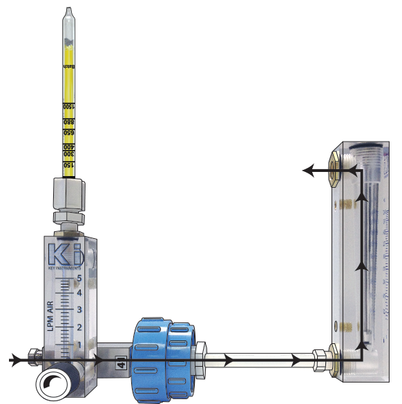
Photo Credit: Trace Analytics, LLC
Water Sampling Tips
To prevent the interference of ambient moisture permeating into the compressed air sample stream, select impermeable materials, such as polished stainless steel or PTFE. Avoid using hygroscopic materials like rubber, as these materials can allow ambient moisture to permeate into the tubing and affect the results. The use of polished or electro-polished stainless steel is important to prevent any water from collecting on the inner surface of the sampling apparatus.
Any type of connection between the sampling apparatus and the sampling outlet should be short, straight and without dead ends. Avoid the potential for leaks by limiting elbows, tees, and valves.
Total Oil Testing
There are so many different words to describe oil. To name a few, common terminology includes condensed hydrocarbons, oil mist, oil aerosol, oil vapor, total gaseous hydrocarbons, and total volatile hydrocarbons—and the list goes on. Oil aerosol is frequently referred to as condensed hydrocarbons or oil mist with limits/results noted in milligrams per cubic meter (mg/m3). Oil vapor or gaseous hydrocarbons are frequently noted in parts per million (ppm). ISO 8573-1 combines both oil aerosol and oil vapor for total oil and is reported as mg/m3.
ISO 8573 has a few definitions that help clarify which hydrocarbons are to be tested:
- Oil: A mixture of hydrocarbons composed of six or more carbon atoms (C6+)
- Oil Aerosol: A mixture of liquid oil suspended in a gaseous medium having negligible fall velocity/settling velocity
- Organic Solvent: A mixture of or a combination of the following identified groups: alcohols, halogenic hydrocarbons, esters, esters/ether alcohols, ketones, and aromatic/alphatic hydrocarbons
- Wall Flow: The proportion of liquid contamination no longer suspended within the air flow of the pipe
Oil Aerosol Testing per ISO 8573-2:2007
ISO 8573-2 describes Method A and Method B for collecting oil aerosol and oil liquid samples. Oil vapor is discussed in 8573-5. Method A is intended for sampling where heavy contamination levels exist, wall flow is present, and the contamination level is between 1 mg/m3 and 40 mg/m3. The liquid oil is collected with two high-efficiency, coalescing filters (one is a backup). Typical testing time is between 50 and 200 hours.
Method B consists of two separate techniques—B1 for full flow, and B2 for partial flow sampling. Both techniques are intended for oil contamination levels between 0.001 and 10 mg/ m3. Typical testing time is between 2 minutes and 10 hours, depending on the flow rate, the pressure available, and the oil purity class limit.
In general, the sampling procedure includes valves, the membrane holder, and the ability to measure flow rate, temperature, and pressure. Three high-efficiency membranes are stacked inside the membrane holder. The membrane must have a surface mass of 80 to 100 g/m2, particle penetration of <0.0005 percent, and have a sturdy support base. In addition, Method B2 uses a straight sampling probe for partial flow sampling under isokinetic conditions. The distribution piping must be altered to allow for the insertion of the probe while maintaining identical velocity conditions.
Trace uses sampling method B1, as it is less intrusive and can be used at various points of use. A minimum air volume of 5,000 liters is required to meet class 1 purity level of 0.01 mg/m3. Other purity classes require 500 liters of air or less.
The analytical method in ISO 8573-2 requires dissolution of the oil on the membrane by an unspecified solvent and analysis of the resulting solution by infrared spectrometry. Trace’s analytical technique gravimetrically determines oil by using pre-weighted membranes. After sampling, the membranes are weighed, extracted with n-pentane, and re-weighed.
Oil Vapor and Organic Solvent Content Testing per ISO 8573-5:2001
This section specifies collection of oil vapors consisting of hydrocarbons with six or more carbon atoms (C6+) on a charcoal tube. Oil vapor analysis is required only for classes 1 and 2.
The primary analytical method is by gas chromatography for vapor content in the range of 0.001 mg/m3 to 10 mg/m3. Chemical indicator tubes can be used only as a preliminary method (they lack the sensitivity and specificity required for quantitation at low levels). Lighter hydrocarbons composed of five or less carbon atoms are not included in total oil purity classes. These lighter hydrocarbons—as well as other gases like carbon monoxide, carbon dioxide, sulfur dioxide and nitrogen dioxide—are addressed in section 8573-6 Gaseous Contaminant Content. There are no established ISO 8573 purity classes or limits for these other gases.
Once again, the sampling procedure calls for a sampling probe, this time being installed into a stainless steel extraction tube filled with coconut charcoal. The sampling procedure as described in Annex A includes a membrane holder installed in front of the stainless steel charcoal-filled tube, a pressure and temperature gauge, valves, and a flow meter. The membrane in this case protects the charcoal tube from aerosol contamination.
Trace uses commercially available charcoal tubes made of glass. These tubes possess the advantages of being less expensive and having a more reliably low level of contamination than laboratory-prepared tubes.
Sampling Tips for Oil
Oil aerosol and vapor are determined at very low levels. Therefore, clean, oil-free fittings are critical for a true determination of airborne contamination. A slight amount of hydrocarbon contamination in a fitting is enough to produce unacceptably high levels of oil vapor (OV) on the charcoal tube. There should be no sudden pressure drops to avoid damaging membranes. Inner pipe diameter should be constant and crevice free—with the size of hole in the ball valve matching the size of piping to avoid loss of oil.
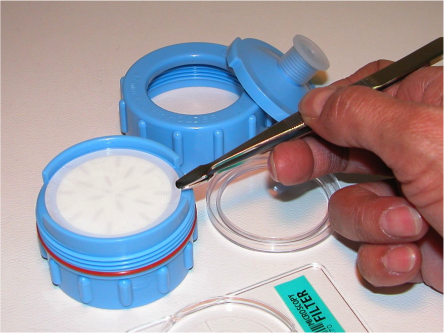
The filter cassette holds three layers of membranes for oil aerosol collection and charcoal tube collect oil vapors. Photo Credit: Trace Analytics, LLC
Avoid cleaning agents with solvents that can affect hydrocarbon content of a sample. Solvents can remain trapped in O-rings and fittings for a surprisingly long time, so only solvents that are not C6+ should be employed. And, as always, ensure that the air compressor inlet is not situated near a source of C6+ materials, such as cleaning baths, solvent waste cans, process solvent/materials, or other ambient sources of hydrocarbons.
If a number of compounds are expected to be present in the ambient or process air, it is best to have the laboratory perform OV analyses using gas chromatography/mass spectrometry, a technique that quite readily discerns between OV and other compounds. These other compounds can be reported separately, thus not impacting the OV level as might occur with gas chromatography with a non-specific detector, such as flame ionization detection (FID).
For more information, contact Ruby Ochoa, tel: (512) 263-0000 ext. 4, email: CDATest@AirCheckLab.com, or visit AirCheckLab.com.
To read more about Food-Grade Air, please visit www.airbestpractices.com/standards/food-grade-air.
References
(1) Particle Measuring Systems, Inc., Basic Guide to Particle Counters and Particle Counting, www.pmeasuring.com.
(2) ISO 8573 specifications referenced above are copyrighted and are available for purchase online at http://webstore.ansi.org/.


