Acrylon Plastics located in Winkler, Manitoba, Canada manufactures an extensive variety of custom plastic parts for a wide range of end use applications including Residential and Commercial Windows & Doors, Buses, Tractors, Combines, Electric Cars, Fencing, Commercial Building Systems and Residential Playground. The production in the Winkler plant using a rotational molding process. Years ago changes to their production volumes increased the compressed air flows to above what their compressed air system could deliver. As a result the plant pressure would fall to low levels during production peak demands, which negatively affected sensitive compressed air powered machines. In addition to this during light plant loading conditions the air compressors would run inefficiently. Plant personnel tried a variety of strategies to deal with the plant peaks, with the most efficient solution coming as a result of installing VSD style compressors and pressure/flow control.
Initial State
When producing large plastic parts with rotary molding process plastic medium is blown into a large mold and the mold is heated and rotated along two axes. In doing this the plastic forms a skin on the inside of the mold and the part that is formed is hollow. The rotating motion prevents the piece from drooping internally while it is forming and cooling. Some of Acrylon’s products are still quite soft when they are cooling and being removed from the mold so an amount of compressed air must be blown into the piece to slightly pressurize it and to cool the inner surfaces. This significant flow of compressed air was pulling down the plant pressure causing poor pressure regulation. Data logging in Chart 1 shows the pressures ranged from a high of 125 psi, the maximum rating of the main compressor, to as low as 75 psi during random production peaks.
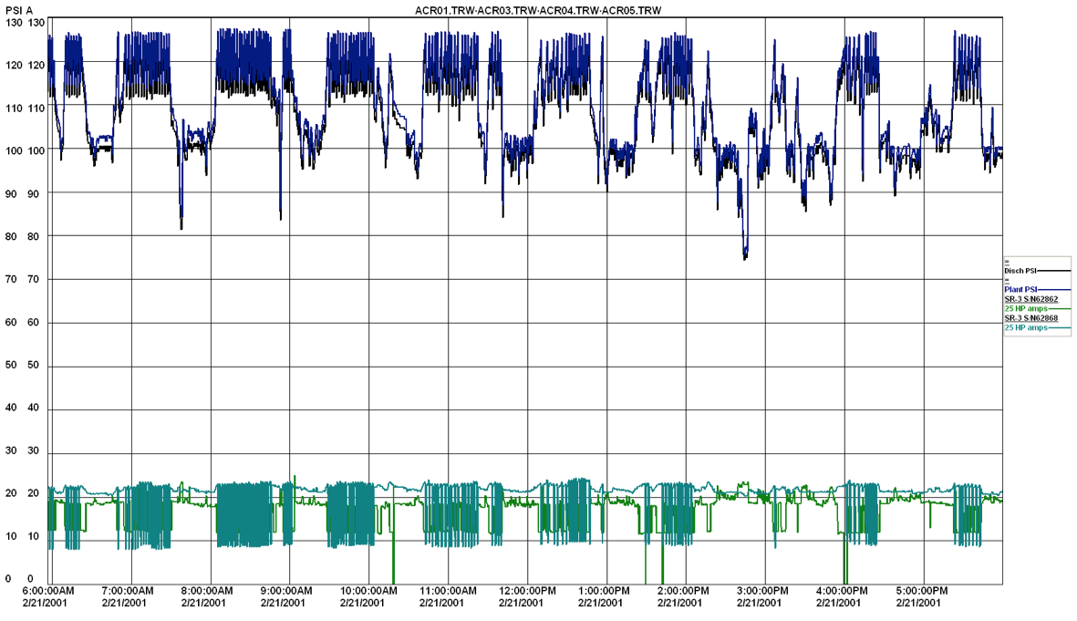
Chart 1: As found data logging with poor pressure control and inefficient compressor operation
Click here to enlarge
Installed at the site were two 25 HP compressors with very little storage receiver capacity. One unit was capable of pushing the plant pressures higher to try to ride out the events, but the other was only rated at 100 psi and had to run in modulation mode with full flow only being produced when the pressure fell to under its rating.
Adding Storage
Acrylon was considering the purchase of a new larger compressor that was capable of higher pressure operation which would store more air in local storage receivers. About this time variable speed drive compressors were being offered by suppliers and Acrylon approached their local power utility to help with the costs because the VSD compressors are more expensive than fixed speed units. The power utility did calculations that showed that the more efficient operation of VSD’s at low loads would pay for the incremental purchase price through significant savings and the power bill.
Acrylon found that a 60 hp compressor was affordable, but due to the high flows involved in processing their parts, some stored air was needed to prevent plant pressure issues. If large air storage wasn’t installed an additional fixed speed compressor would have had to start to support the pressure. This would increase the energy consumption because the unit would run unloaded for significant periods of time.
A 1,060 gallon storage receiver was purchased with a pressure flow controller. The plant implemented a storage strategy where the air compressor would produce compressed air at 135 psi and the plant pressure regulated down to about 90 psi. Whenever the plant flows exceeded the capacity of the main compressor some air was drawn from storage, as seen in Chart 2, rather than starting another compressor. If the pressure/flow controller was not used, in this case, the plant would have seen excessive pressure, causing all pressure sensitive compressed air consumers to use more compressed air (called artificial demand). It can be seen in Chart 2 there are still some occasions where plant pressure falls to lower levels when all the air stored in the receiver has been used up. The solution to this would be to add more storage capacity. These pressure reductions occurred during non critical times due to clean-up activities.
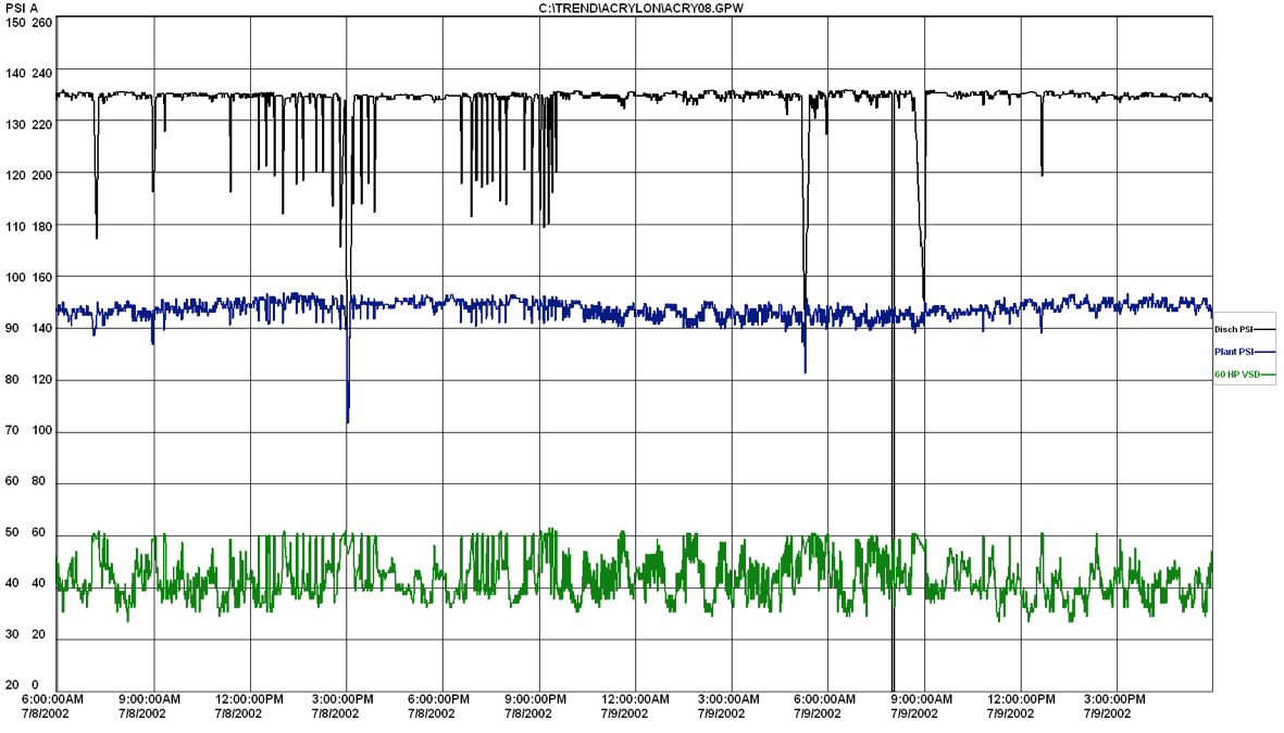
Chart 2: Running high discharge pressure into large storage prevents the start of a second compressor
Click here to enlarge
A disadvantage of this high pressure system of storage is that the discharge pressure of the air compressor is much higher than the required plant pressure. Due to the higher pressure the compressor will consume more energy per unit of flow output. But in this case the energy consumed and the electrical peak demand charges incurred were lower than would have been consumed by a second running fixed speed compressor. The system saved about 46% in energy costs over the base case scenario or adding a third compressor.
Adding a New Compressor
This system worked adequately for many years and eventually Acrylon decided to purchase a second compressor to replace the old fixed speed backup unit. This was an opportunity to enhance the savings of the project due to the characteristics of VSD’s. The previous fixed speed compressor ran in the load/unload mode with auto shutoff. When it started it had to run for a fixed period of time to prevent the maximum allowable number of motor starts from damaging the motor. But VSD’s can start and stop much more often and most are not required to run unloaded for a cool down period.
It was decided to change the system and install a new larger 75 hp VSD compressor. The original VSD was set to provide backup to cover the occasional peak flows. In this case the main VSD does not now have to run at high pressure to store compressed air for later use, the larger capacity plus the backup was enough to fully cover peak flows. This meant that discharge pressures could be reduced so the new system could run with lower energy consumption. The second VSD will start only for the periods of time required to save the system pressure from falling below required levels. Once it is not needed it immediately shuts off with no unloaded run time.
System operation is shown in Chart 3 where the main compressor discharge pressure is now 108 psi. For the data in Chart 3 the second compressor was turned off temporarily but is normally set to start when the storage pressure drops below 100 psi. The system electrical costs for this system were reduced a further 34% due to the lower pressure and the increased efficiency of the newer compressor.
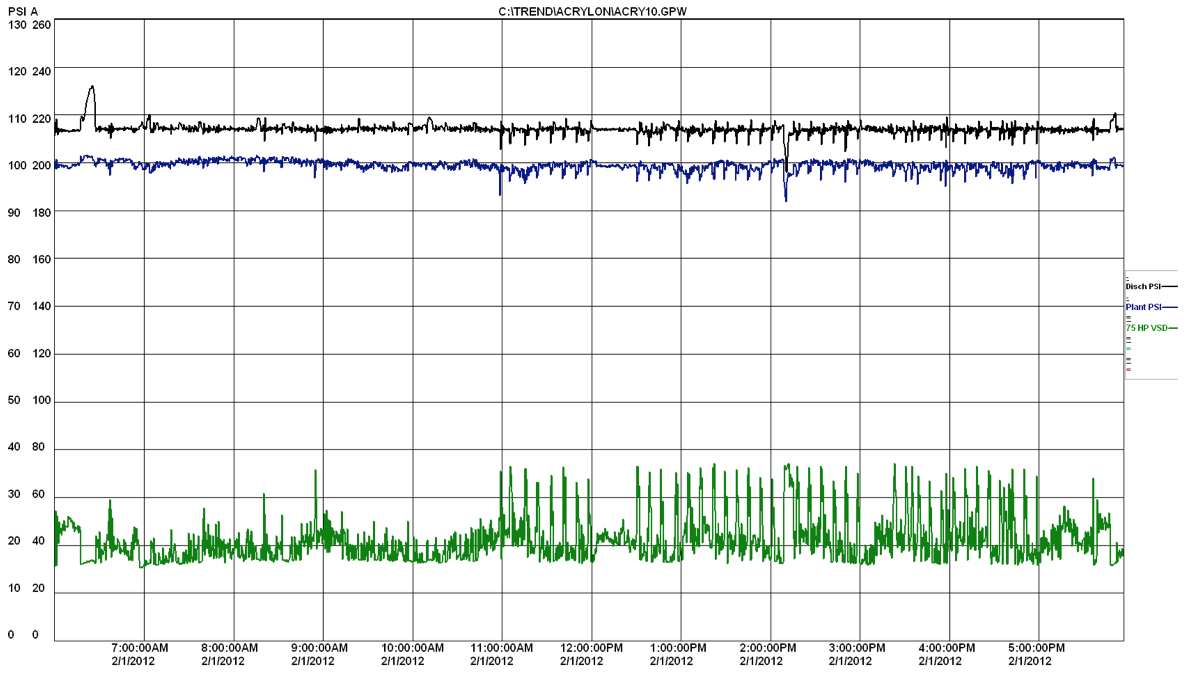
Chart 3: Use of VSD sized for the load set at lower pressure saved energy
Click here to enlarge
Conclusions
This case study shows that a number of strategies can be used to deal with peak flows. Large storage can prevent the start of a second compressor which would boost energy and demand costs. But the excellent characteristics of VSD compressors can be used to further save energy costs if configured correctly to supply peak flows at lower pressures.
For more information visit the Compressed Air Challenge® website or contact Ron Marshall, Marshall Compressed Air Consulting, tel: 204-806-2085, email: [email protected].
To read more Plastics Industry stories, visit www.airbestpractices.com/industries/plastics.