Spruce Products Limited, a sawmill located in Swan River, Manitoba, Canada, operates with five separate compressed air systems in their various buildings. A few years ago a sharp-eyed air compressor service representative noticed the screw compressors on site had less than optimal loading to operating hours ratios. Recognizing this was a problem, he suggested the company get in touch with their local power utility for a free compressed air scoping assessment. As a result, SPL has optimized two of their compressed air systems to-date, saving significant operating costs. One system is operating at 86% less energy consumption than previous levels.
Background
The company, operating since 1942, produces kiln dried, treated and green rough lumber primarily for the Canadian market. Important byproducts are wood chips, wood shavings and softwood lumber pellets. The air compressors in each building operate on a 5-day a week 10 hour production shift, with pressure typically being maintained overnight for maintenance activities. A compressed air system in a boiler house in the complex runs on a 24 x 7 basis to feed boiler controls and soot blowing. Biomass is used to supplement the boilers to provide heat for lumber drying operations.
Separate compressed air systems are maintained in each of five buildings on the site. These are:
- New Mill – Three 50 hp load/unload air-cooled lubricated screw air compressors operate with cascaded pressure bands. Three 240 gallon receivers are located at various points on the system to help with compressor control.
- Old Mill – One 50 hp load/unload air-cooled lubricated screw compressor operates the old mill, the compressor has one 240 gallon main storage receiver. A weak connection between old and new mill exists, but it is too small to enable the shutdown of the old mill compressor.
- Planer – One 50 hp load/unload air-cooled lubricated screw compressor operates with a 240 gallon storage receiver, but with a narrow pressure band setting causing rapid cycling.
- Boiler Building – A 30 hp load/unload air-cooled lubricated screw compressor feeds boiler controls and a soot blowing application on a 24 x 7 basis. The system runs with three 120 gallon receivers.
- Packaging – A small 25 hp two-stage reciprocating compressor with non-cycling refrigerated dryer feeds a packaging building.
None of the main air compressors have compressed air dryers or main filters. The piping systems in the mills have been designed with well thought out drainage to enable untreated air to be used for pneumatic applications. The lack of dryers reduces the pressure drop in the compressor room.
The following table shows the operating hours discovered by the service representative:
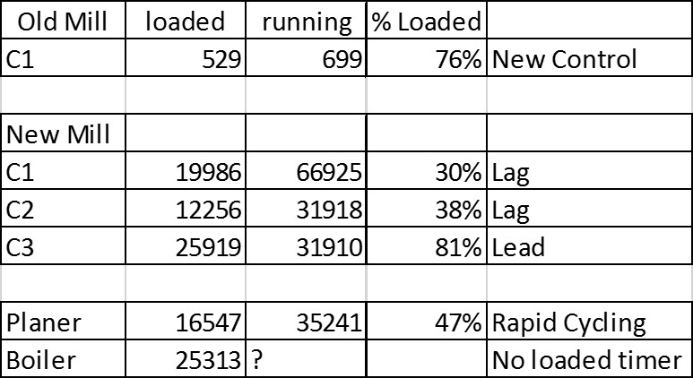
Figure 1: Operating Hours Survey
The operating hour readings suggested that two of the three of the systems were lightly loaded, site observations by the salesman confirmed the fourth in the boiler room was running unloaded most of the time. Based on this, a more thorough assessment of all systems was done using data loggers. Figure 2 and 3 show the operation of the two most important systems.
The compressors in the main mill were not operating in a well-coordinated manner. Most of the time during production, when only two compressors were required, there were three running. Unintended shutdowns were occurring, causing low pressure due to the poor condition of one of the compressors. High load was detected during non-production hours, suggesting unacceptable leakage losses and rapid cycling of the main compressor.
In the boiler building, the data loggers showed the main compressor was running very lightly loaded, but never turning off. This accumulated significant wasteful unloaded run time, where the compressor consumes power, but produces no air. Transient dips in pressure caused by soot blowing blasts drew down discharge pressure to lower levels, but this did not affect boiler operations.
The following table shows the baseline readings of the main systems:
|
Bldg |
HP |
kVa |
kWh |
$ Cost |
Pk cfm |
Ave cfm |
kW/100 |
|
New Mill |
3 x 50 |
159 |
392,230 |
$34,365 |
700 |
300 |
22.0 |
|
Old Mill |
50 |
32 |
104,815 |
$9,390 |
120 |
111 |
29.2 |
|
Planer |
50 |
39 |
98,000 |
$8,460 |
115 |
60 |
43.3 |
|
Boiler |
30 |
13 |
73,584 |
$4,560 |
24 |
9 |
89.3 |
|
Total |
280 |
243 |
668,629 |
$56,775 |
959 |
480 |
|
Figure 2: Baseline Energy and Cost with specific power
The total compressor energy consumption of all the compressed air system combined was estimated at about 12 percent of the total electrical consumption of the facility. It can be seen that the specific power (kW/100 cfm) of the various systems varies widely from a low of 22 kW/100 cfm to an extremely high value of 89 in the Boiler Building. These numbers suggested there was a significant potential for system efficiency improvement if the compressor control was changed to VSD mode. Further reductions in energy consumption could be gained by reducing compressed air leaks or optimizing end uses.
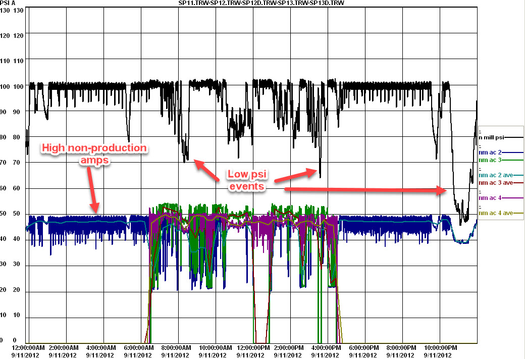
Figure 3: Original pressure/amp profile – New Mill - Click here to enlarge
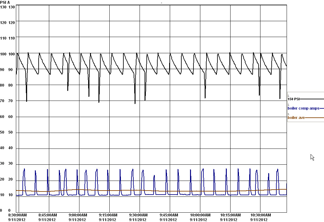
Figure 4 – Original Boiler Building profile - Click here to enlarge
The power utility, Manitoba Hydro estimated total possible savings of 36 percent could be gained by adding VSD compressors to the various systems.
Project Results
SPL decided to start the improvement process by first upgrading the systems in the New Mill and the Boiler Building. A 75 hp VSD compressor was selected for the New Mill to work with the existing 50 hp fixed speed units. Selection of a VSD unit larger than the base compressors makes control of the compressors much better, as it avoids a control gap problem, allowing the VSD to run continuously within its regulation band. The VSD target pressure in these cases is typically nested within the cascaded load/unload pressure bands of the fixed speed units for a very well-coordinated control strategy, with more stable pressure.
When the system was verified, there were some unexpected problems. The data logging of the original setup showed the coordination was less than optimum as there were periods of unacceptable unloaded run time for the base compressors, and some unexpected compressor operations during non-production hours. The problem was traced to a pressure transducer out of calibration, the actual reading was about 4 psi different than the control value. This caused the pressure band coordination to be less than optimal, causing some undesired interaction between the base and VSD compressors where the units would fight for control. Correction of the calibration brought the system under control and minimized the unloaded run time of the base units to less than 3 percent. Together the base units combined run duty is about 40 percent of the time, with the VSD supplying the main plant flows as the lead unit.
During non-production periods some high flow short duration pulses were detected that were affecting the operation of the compressors. Occasionally when this high flow triggered, during times when the system was lightly loaded, a second unneeded compressor would see the pressure change and start and run unloaded in anticipation it would be needed. This problem was traced to a timed blowing operation shown in Figure 5 where the coils of an air conditioning unit were cleared of sawdust contamination to improve ventilation. This air conditioning unit was used to cool an electrical room containing critical electronic controls, and as such the plant personnel were hesitant to completely remove it. The operation was modified so the high flow blast was fed by air stored in two receivers, with the flow of air feeding the receivers metered in slowly between blasts, eliminating the large flow step change. This eliminated the unwanted compressor starts.
Final verification of this system found the optimized system was consuming about 29 percent less energy than previous, and the plant pressure was running at a more constant level.
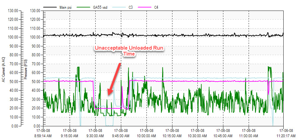
Figure 5: Verification of New Mill VSD installation showed problems - Click here to enlarge
In the Boiler Building, a small 25 hp VSD compressor was installed and the old 30 hp load/unload unit retired to standby duty. The small unit runs in start/stop mode during light loads, but runs at full speed whenever it needs to supply soot blowing operations. This reduces compressor run time to about 24 percent compared to running 100 percent of the time, mostly unloaded, with the old compressor. This eliminated the wasteful unloaded run time making the previous operation so inefficient. Final verification found the new system was consuming slightly more than 10,000 kWh per year, for a reduction of 86 percent compared to the original baseline. The completion of both projects resulted in both a reduction in operating costs and a substantial utility incentive to help pay for the new compressors.
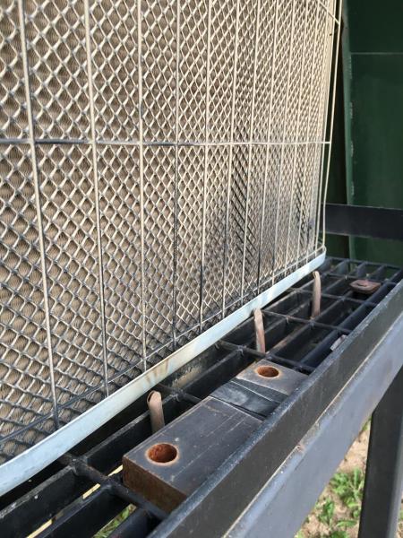
Figure 6: An air conditioning unit was cleaned by a timer controlled blast affecting air compressor control
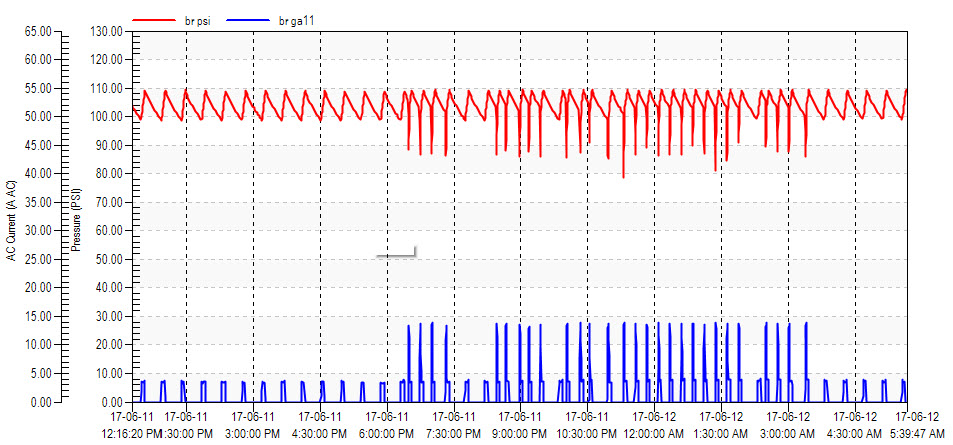
Figure 7: The boiler compressor now only runs 24 percent of the time with no unloaded run time - Click here to enlarge
Other Changes
SPL staff are considering further changes to their system, as budget allows:
- A connection between the old and new mills may be upgraded so the two systems can be combined into one efficiently operating system.
- A new VSD compressor is being considered for the Planer area.
- The reciprocating compressor in the Packaging area will be converted to a similar style VSD compressor as used in the Boiler Building. This will result in a slight reduction in energy, as a lubricated screw is more efficient at full load than a small air cooled reciprocating compressor. Compared to a load/unload screw, an option that could have been taken, the VSD compressor is much more efficient, for the reasons shown in the Boiler Building project. The new compressor will also be outfitted with a cycling dryer, reducing the energy consumption of the non-cycling existing unit.
- Staff are considering changes to condensate drainage to eliminate the waste from constantly operating timer drains.
- Some open blowing in the planer area is being looked at for optimization.
- Leakage reduction strategies are ongoing.
Conclusion
The results of this assessment, and the projects generated, show the value of having well trained sales representatives look at your system. Often there will be potential opportunities for savings that are not obvious to plant compressor operators. More precise measurement with data loggers can bring these savings to light and set up the projects so they can be supported by local energy incentives. This plant is just another example of how this can work in an excellent manner.
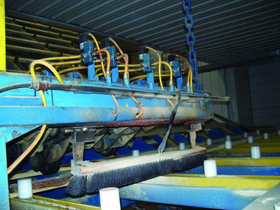
Figure 8: Both compressed air blowing (pipe with holes drilled) and mechanical broom power are used to clear wood chips from lumber pieces. Guess which uses less energy.
For more information contact Ron Marshall, Marshall Compressed Air Consulting, tel: 204-806-2085, email: [email protected].
To read more System Assessment articles please visit www.airbestpractices.com/system-assessments.