The intent of this article is to provide readers with simple examples of calculations one can perform to evaluate two sample energy efficiency projects for compressed air systems; pressure sensing vortex vacuum generators and outside air intake (for air compressors).
Project #1: Pressure Sensing Vortex Vacuum Generators
While creating a vacuum with compressed air is inefficient compared to using vacuum pumps, vortex vacuum generators are ubiquitous for small volume applications. These are commonplace for robotic parts movement and packaging machines using suction cups. Their compact size, high degree of control, and low cost make them an attractive solution for providing the suction needed at the end of robotic arms to move parts, and the modest compressed air demand can generally be accommodated by existing compressed air plants.
The ability to use compressed air to create this vacuum only when needed based on pressure instead of running constantly while the vacuum is in use represents an energy savings.
Compressed Air Savings
Manufacturer claims reach up to a 90% reduction in compressed air use2. However this is highly dependent on the cycle time and the amount of vacuum loss in the system. The system vacuum loss depends on the porosity of the surface for suction cups and the amount of leakage. When idle and waiting on parts, compressed air flow is shut off. While the manufacturer claims are likely to be correct, it applies to situations where the cycle and hold times are long. In this type of case, maintaining the vacuum would account for a much larger portion of the cycle than initially evacuating the system.
Articles in Compressed Air Best Practices describe one case study on a corrugated cardboard handler where suction cups were used at the end of a robot arm identified 30-50% savings3. An automotive case claimed 98% savings4 for a sheet metal handling application.
The Consumers Energy Business Energy Efficiency Program conducted a study at a plastics parts manufacturer on a single production cell with three vacuum generators. The production cell consisted of an injection molding machine served by robotic removal of parts from the molding machine. An external data logging compressed air flow meter was used to record air flow with the original vacuum generators and the new pressure sensing vacuum generators. The number of production pieces during the monitoring periods was tracked in order to establish compressed air use per piece, and the nominal rate is about 3,000 pieces per day (or two per minute). The original flow recording is shown in the graph below:
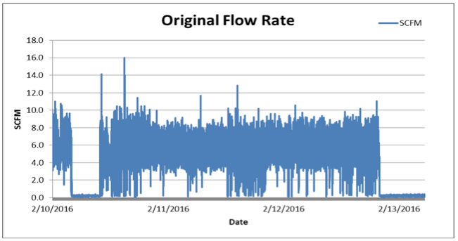
The production during this period was 9,338 pieces.
The average compressed air flow rate was 5.55 scfm.
And the amount of compressed air consumed was 19,257 standard cubic feet.
Dividing the compressed air use by the production creates a metric of 2.062 ft3/piece.
Monitoring was repeated after changing to pressure sensing vacuum pumps. The new flow recording is shown in the graph below:
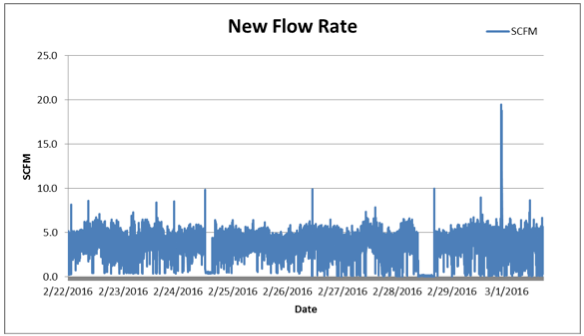
The production during this period was 26,683 pieces.
The average compressed air flow rate was 3.469 scfm.
And the amount of compressed air consumed was 43,261 standard cubic feet.
Dividing the compressed air use by the production creates a metric of 1.621 ft3/piece.
The percentage savings for the metric in this case is given by the following:
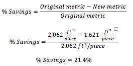
At a production rate of about two pieces per minute, this system would have a brief hold time for the parts which is a case where the pressure sensing technology offers the least advantage, but savings were still demonstrated.
Calculating Percentage Savings
The documented savings vary from 21% to 98% of compressed air use when applied to production systems. This wide variation suggests that users wanting to estimate a payback should first obtain the run time of the vacuum generator. When hold times are brief or there is leakage due to porous surfaces or worn cups, then the savings percentage will be lower.
As an example, assume that 60% savings are obtained during the time the basic vacuum generator is running. Further assume that the generator runs half the time and is idle (off) the other half and there is no air flow. A savings can be predicted based on the rated compressed air consumption of the vacuum generator.
![]()
Vacuum pumps vary in size, so this is done based on 1 cfm of rated compressed air flow for the vacuum generator. The average cfm savings are thus given by the following:
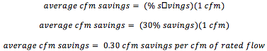
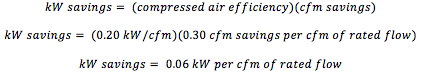
Compressed air generation efficiency is taken to be 0.20 kW/cfm. So the kW savings become the following:
For a three shift operation of 6000 hr/yr this becomes 360 kWh per cfm of rated compressed air flow capacity. Typical compressed air flow capacity is 1-10 scfm for each vacuum generator. For a vacuum generator rated to use 3 cfm and an electricity cost of \$0.10/kWh, the annual savings would be 1,080 kWh and \$108.
The cost of each of the three pressure sensing vacuum generators in the Consumers Energy study was under \$300, so these are relatively inexpensive and can offer a reasonable payback. When replacing the conventional vacuum generators, the incremental cost to upgrade to pressure sensing vacuum generators will be even less. While each individual vacuum generator may have a modest amount of compressed air use, this is a compressed air best practice that can have a facility impact when deployed over an entire site with dozens of vacuum generators.
Project #2:: Outdoor Air Intake Calculations
Many recognize there is a modest efficiency gain by using an outdoor air intake to the air compressor instead of using warm plant air. Sometimes the air compressor inlet air is even taken from hot compressor rooms. One rule-of-thumb is there is a 1% energy savings for every 10°F drop in inlet temperature.4
The basic principle for this is cooler air is denser, so the air compressor has to perform less work to reach the desired air pressure. Typically, outdoor air temperatures are lower than plant or air compressor room temperatures, so there is a savings by ducting outside air to the compressor inlet. The amount of compressor work is proportional to the absolute temperature of the intake air. The reduction in work resulting from lowering the intake air temperature is given by the following formula and example:
Wreduction = (TIndoor - TOutdoor) / TIndoor
Where:
Wreduction = Work reduction, no units
Tindoor = Indoor air temperature at the compressor inlet, 80°F + 460 = 540°R
Toutdoor =Average outdoor air temperature, 55°F + 460 = 515°R
Here it is assumed that the compressor room temperature is 80°F and the average year-round outside temperature is 55°F. The temperatures are converted to an absolute temperature in Rankine.
Wreduction = ( 540°R - 515°R ) / 540°R
= 0.0463 or 4.63%
Applying this to various temperatures from a baseline of 80°F produces the following table:
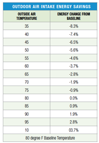
The annual savings can then be estimated from an estimate of the air compressor energy use multiplied by the percentage savings. For example a 100 hp VSD air compressor may draw an average of 50 kW for 4000 hours a year thus using 200,000 kWh and costing \$20,000/yr in electricity at a price of \$0.10/kWh. A 5% savings would be worth about \$1,000.
Implementation
As with any project, the cost to implement this has to be reasonable since the savings may be modest. A great many air compressor rooms are located on outside walls or in sheds which helps keep the duct run short and less costly. A screen to keep out animals and debris may be useful. A few ways that can help keep the installation cost reasonable include the following:
- Include the outside air intake as part of a larger project for new construction or new compressor acquisition.
- Use flex duct between the compressor inlet and the outdoors. The inlet to many compressors is several inches, and flexible ducting may fit and take little labor to install.
- Where a compressor already pulls in outside air for cooling, duct from the intake side of the cooling duct to the compressor inlet. This is a very short run.
Using an outside air intake for the compressor inlet air is a compressed air best practice. It offers modest savings, and where the installation cost is reasonable can provide a good return on investment.
For more information contact Jerry Zolkowski, PE, CEM, Senior Engineer, Consumers Business Energy Efficiency Solutions, tel: 517-481-2972, email: [email protected], www.consumersenergy.com.
To read similar End Use System Assessment Articles visit www.airbestpractices.com/system-assessments/end-uses.
Sources of Information
1. SMC brochure for SK2 product line. Accessed on 7/7/2016. https://content2.smcetech.com/pdf/ZK2.pdf.
2. Handling Corrugated Cardboard with Optimized Pressure-Regulation of Air-Driven Vacuum Pumps. Accessed on 7/7/2016. www.airbestpractices.com/industries/food/handling-corrugated-cardboard-optimized-pressure-regulation-air-driven-vacuum-pumps.
3. Chrysler Finds Vacuum Savings of \$400,000 per Plant. Accessed 7/7/2016. www.airbestpractices.com/industries/auto/chrysler-finds-vacuum-savings-400000-plant.
4. Sanity Check: Will the Standby Air Compressors Start-Up During Cold Weather? Accessed on 7/12/2016. www.airbestpractices.com/technology/air-compressors/sanity-check-will-standby-air-compressors-start-during-cold-weather.