The Compressed Air Challenge® Fundamentals and Advanced training discuss the benefits of using central controllers to efficiently control system compressors. These systems are called “System Master” controls. Modern day System Master Controls use advanced technologies to network air compressors in a preprogrammed sequence. A properly configured network with the right size and type of trim compressor can typically hold the supply air pressure in a tight band of +/- 2 psi. Because of this capability, many users feel the application of System Master Control negates the benefit of applying Pressure-Flow Control to stabilize the plant air pressure.
Pesure-Flow Control Ensures a Reliable Stable Source of Air Is Always Available to Production
In a recent survey conducted by the Department of Energy, 71% of the people reported reliability as the most important objective in a compressed air system.* Air quality and controlling costs followed in the order of priorities at only 12% and 9% respectively. Plant personnel weigh reliability very heavily when evaluating changes, upgrades, and energy efficiency improvements. Consider the following scenario.
To comply with Corporate’s new reliability standards, two new variable displacement rotary screw compressors with poppet valve control were purchased and installed as the priority lead compressors. The existing compressors were relegated to low priority standby status to act as back up compressors to the primary units. A System Master Control was installed to network the compressors. The System Master Control sensed the pressure in the common receiver and, by taking advantage of the poppet valve control on the new rotary screw compressors, held it +/- 2 psi. Everything was stable and balance point pressure at the main header supplying the plant was held at a minimum acceptable level to sustain production under all operating conditions. Then an unanticipated failure of the lead priority compressor occurred resulting in a rapid decay in the supply pressure. The System Master Control sensed the decline and called for the next compressor programmed in the sequence to start and load. As the standby compressor came on line, ran through its permissives, and began to contribute air, the supply pressure continued its rapid decline. Because the event occurred when pressure was at the bottom of the band, critical processes began to approach automated shut down due to the low pressure condition. Had the pressure fallen below the minimum acceptable pressure the lost production would have been very costly.
Fortunately, the actual system in the above example was equipped with Pressure-Flow Control as an additional safeguard to ensure reliability. The Pressure-Flow Control released supplemental air from the storage receiver to sustain production through the duration of the event. Production never saw the pressure dip and was not even aware that an event had occurred. The Pressure-Flow Control paid for itself by preventing work stoppages because of the unanticipated compressor failure.
Pressure-Flow Control: The Science is Simple.
The term Pressure-Flow Control is the generic name chosen by the Compressed Air Challenge to describe a system consisting of:
- A large air storage receiver.
- Precision motor driven control valve.
- Pressure transducer or pneumatic servo pilot device.
- Control panel.
The arrangement uses the controlled release of air already in storage to stabilize the air pressure delivered into the main piping header leaving the compressor room. Pressure at control valve outlet is sensed and air flow is continuously adjusted to correct the deviations from set point. It works on the principle that when compressed air expands, the pressure decreases and, conversely, when air compresses, the pressure increases. Therefore, if more air is flowing away from the balance point than in, the pressure goes down and the control valve modulates open to release more air from storage to bring it back to the set point. The opposite action occurs if more air is flowing into the balance point than away as the valve modulates closed to hold air back in storage. Figure 1 is a schematic illustration of a typical arrangement.
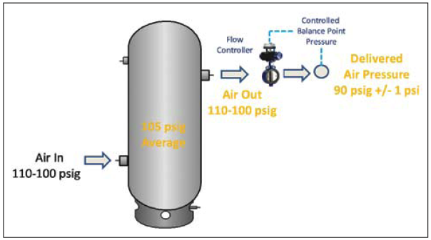
Figure 1: The control valve releases air from storage to correct for pressure deviations.
Understanding the Concept of Useable Storage
Volume alone does not equate to useable air storage. There must also be a corresponding change in pressure to increase or release the energy content imparted in the stored air during the compression process. Consider the condition as depicted in Figure 2.
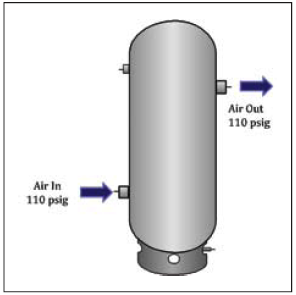
Figure 2: No storage is created if pressures in and out are equalized.
Pressure “in” is the same as pressure “out”. There can be no flow through the receiver. A quiet zone has been created but no useable storage. If the pressure on the outlet changes, the pressure on the inlet will also change and instantaneously equalize. While the receiver adds volume and, as such, potential energy to the system, the energy released from storage is a result of the pressure gradient across the entire plant air system and is not useable for controlling and stabilizing the pressure of the delivered air leaving the compressor room. If no further steps are taken, the addition of only volume will reduce pressure variations, smooth out rates of change, and buffer the control response of the compressors. It will not, however, stabilize and allow a reduction of the delivered air pressure. A Pressure-Flow Control will be required if the goal is to lower the plant air pressure beyond the capability of readjusting the discharge pressures at the compressors.
The benefit from applying Pressure-Flow Control is that the plant air pressure can be maintained the lowest optimum level needed to reliably sustain production. The example depicted in Figure 1 shows the delivered air pressure is reduced from 105psig on average +/- 5psi to a stable steady 90psig +/-1psi. The use of the Pressure-Flow Control to lower pressure instead of simply adjusting the compressor pressure settings ensures air treatment equipment performance does not deteriorate. The immediate pay back is less air is consumed by leaks and unregulated points of use. The savings amounts to a flow reduction of about 1% per psi reduced.
Pressure-Flow Control also prevents the plant air pressure from rising as leaks are repaired and air waste is reduced. If nothing is done to control the pressure, it can creep up and cause more air to vent out of other escape points in the system such as condensate drains, open air blowing devices, unrepaired leaks, and unregulated points of use. There are also operational savings from reducing leak demand and optimizing air use. Air flow across filters and dryers will be less. Pressure drops in the piping distribution system will decrease. Maintenance costs will go down. Pressure-Flow Control is an excellent tool to use for controlling air leakages of all types.

Operate at the Minimum Pressures Needed to Sustain Production.
The air supply pressure into the receiver is determined by the compressor settings. The air pressure in the receiver at any point in time is determined by the flow of air into the main header supplying production. With the delivered air pressure held steady at a reduced level, the opportunity to lower the discharge pressure at the compressors becomes available. The savings amount to about a 1 percent power reduction for every 2 psi of compressor discharge pressure reduction. This is in addition to the already mentioned flow reduction.
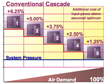
Figure 3 shows the typical pressure band in a conventional cascade arrangement.
Figure 3 depicts a conventional cascade style of pressure settings for a multiple compressor setup. Note additional input power of between +1.25 and 6.25% incurred due to operating at pressures above the optimum system pressure. Also, the lower the air demand, the greater the inefficiencies because this results in higher average pressure.
Tightening and lowering the pressure band will reduce the power requirements based upon satisfying demand but there is a risk of short cycling the lag compressors or forcing them to operate unloaded rather than shutting down. An unloaded operating compressor will use 25-40% of its full load energy without contributing any air to the system. Running unloaded is much more inefficient than slightly over pressurizing The application of Pressure-Flow Control allows the compressor to operate within a wider pressure band which mitigates the short cycling and allows unloaded compressors to time out and shut down. Compressors no longer have to react to the peak short duration demand events because these are now satisfied with air from storage. In most systems, the storage required to cover the unanticipated failure of an operating compressor will be sufficient to cover surge loads. It should be checked using the following equation.
Vs = Vf x âP/Pa
Where Vs = stored event volume (cubic feet)
âP = change in pressure allowed for event (psi)
Pa = atmospheric pressure (psia)
Vf = fixed volume (cubic feet)
Convert the calculated fixed volume and pick the next largest standard stock size receiver.
7.48 gallons/cf x Vf = gallons
While the application of Pressure-Flow Control improves the part load efficiency of compressors operating in a cascade pressure profile, greater savings can be realized from the application of System Master Control to network the compressors as illustrated in Figure 4 and operate with a single pressure band.
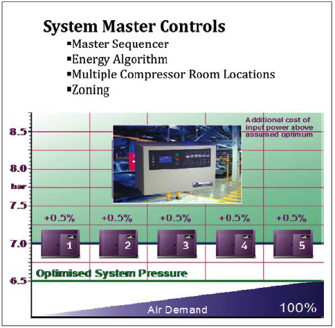
Figure 4: System Master Control networks compressors in a preprogrammed sequence.
Note the additional required input power remains at only .5% above the optimum regardless of the demand load.
System Master Controls are available in many different arrangements at prices to fit most budgets. Basic sequencers using timer rotation are designed for smaller systems and can be economically justified with compressors as low as 15hp. More sophisticated designs incorporate real time sequencing schemes allowing for table technology scheduling and energy algorithms to take advantage of the latest energy efficient VSD and Variable Displacement compressor control arrangements. More complex System Master Controls can deal with multiple compressor rooms using pressure averaging and pressure zoning of a plant in the sequencing scheme. In most systems, Pressure-Flow Control will enhance the performance of System Master Control by isolating the compressor response from the dynamic demands, allowing them to sequence in the most efficient manner instead reacting and chasing the system. Figure 5 is a representation of the final layout for the system described in the opening example of how Pressure-Flow Control can enhance the reliability of the plant air system.
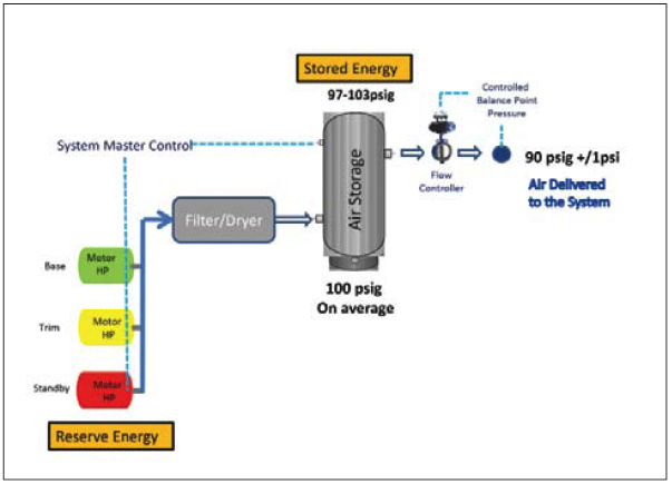
Figure 5: The final configuration
A number of factors must be considered in determining the best configuration for a specific system. The objective for every system is to operate at the minimum pressures needed to reliably support production. Deliver air at the lowest possible pressure to minimize waste due to leaks and unregulated uses. Then set the compressor pressure band as low as possible, consistent with the reliable operation of the compressors. For this example, the variable displacement compressors were equal in size and the poppet valve control suggested a 6 psi pressure band would be adequate to ensure the reliability of the system. The Pressure-Flow Control supplements the air supplied by the compressors while the System Master Control draws upon the reserve energy of the trim compressor and standby compressor, if necessary. Air storage is sufficient at the 90 psig outlet pressure/7-13 psid to cover an unanticipated failure of an operating compressor. The savings from lowering the plant air pressure and networking the compressors with System Master Control amounts to about 20%. Plus, a production interruption due to a catastrophic event was avoided. The investment in the Pressure-Flow Control produced a good return. A different mix of compressor types and sizes would have different requirements to consider and the configuration could be quite different. Every system must be reviewed and the alternatives must be explored to determine the best way to deal with the site specific conditions. Pressure-Flow Control should be included in the evaluation process as a means to:
- Ensure a reliable stable source of air is always available to production.
- Reduce waste and inefficiencies due to leaks and unregulated air use
- Save energy.
- Allow consumption savings to translate into real dollar cost savings.
- Enhance the automated sequencing of networked compressors.
In Summary:
Pressure-Flow Control interconnects the supply side of the system with the demand side and becomes the device that maintains the energy balance at an optimum level at all times, under all operating conditions. It does this through the controlled release of air stored in an upstream receiver. The compressors generating the air sense the pressure in the receiver and proactively replenish the supply to maintain the level of stored energy and ensure the system integrity. The total energy required by the system constantly changes and therefore must be supported by a method that can vary and quickly adjust to the changes. Pressure-Flow Control does this and, in combination with applied energy of the compressors, allows the plant air system to operate reliably at an optimum energy balance. Most compressed air systems will benefit from the application of Pressure-Flow Control. The potential for improving the energy efficiency and reliability of the system justifies looking at a system upgrade to include the addition of Pressure-Flow Control.

To read more System Assessment articles, visit www.airbestpractices.com/system-assessments/pressure.