
 |
System Assessment of the Month |
|---|---|
| Company | Roxane Laboratories |
| Where: | Columbus, Ohio |
| Industry: | Pharmaceutical |
| Issues: |
* Excessive energy costs * Routine equipment failures * Plant intends to expand production; the air system cannot increase delivered air |
| Audit Type: |
Supply, Piping and Demand Side |
| System Assessment Win/Win Results | |
|---|---|
| Annual Energy Costs Before Assessment | $102,453 |
| Annual Energy Costs After Assessment | $42,139 |
| Annual Energy Savings | $61,314 |
| Reduction in Electrical Energy | 1,156,868 kWh |
| Equivalent CO2 Emissions | 824.84 metric tons |
| Equivalent CO2 for Homes | 109 Homes |
| Equivalent CO2 for Vehicles | 151 vehicles |
In early 2003, Roxane Laboratories, Inc., a subsidiary of Boehringer Ingelheim Corporation located in Columbus, Ohio, was charged with planning and implementing a major plant expansion to take place over the following five years. As plans progressed, the project team found that one of the most significant limitations to this expansion was the inability to increase air flow to the plant with their existing compressors. When plant personnel imposed a false additional demand on the system, the compressed air system could not hold the plant pressure, even with all the units running.
Roxane Laboratories contacted the service provider they used at that time (Air Power of Ohio), who called an independent compressed air consulting group, Air Power USA, Inc., from nearby Pickerington, Ohio.
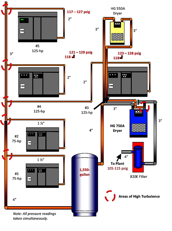
Air Power USA’s findings concluded that the basic piping configuration and sizing was limiting the ability of the system to deliver any additional air from the compressor room to the plant. See Figure 1.
Figure 1.
Roxane Laboratories Compressor Room
Roxane Laboratories contracted with Air Power USA to conduct a complete review and audit of their system including all the production areas on the demand side. They also requested a detailed plan to double the effective size of the air system and produce “a world class” compressed air system which reflects the high quality standards of the company.
The Audit / Review Begins
Air Power USA personnel installed kW recording meters on each of the three air-cooled 125-hp class, 2-stage oil-free rotary screw compressors. Each of these units is capable of delivering 498 acfm (448 scfm) at 125 psig full flow pressure at 130.2 BHP (104 kW with a .93 ME motor). The actual measured input kW was: Unit #3 – 110 kW; Unit #4 – 109 kW; Unit #5 – 105 kW.
Air delivered to the system was measured and logged by a heated wire insertion flowmeter. Data was recorded and collected for seven days to capture all operating conditions. The plant runs 24 hours a day, 7 days a week for 8,760 hours per year. There are many separate operations in production that are very well controlled. The flowmeter ranged from 650 to 1,250 scfm sustained peak with an average of 725 scfm.
The air compressors were equipped with 2-step, or load/no-load capacity controls, which operate on a 10 psig band (nominal 115-125 psig). The unit is at full load as the pressure (and input kW) increase along the band. At the unload point, the compressor inlet valve closes and the unit input kW falls to idle (24 kW).
The compressors capacity control system was set up in a typical cascade system as shown in Figure 2. Reviewing the schematic in Figure 1, the units on line are #3, #4 and #5.
Figure 2.
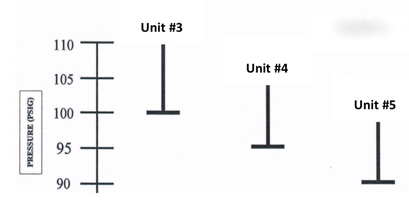
Figures 3 and 4 reveal trended kW measurement of three 125-hp units at Roxane Laboratories. All readings were taken simultaneously and are shown in two sets for clarity; however, you will note that Unit #5 is always at base load, and Unit #3 short cycles in trim. Unit #4 tries to load in but cannot forcing Unit #3 to turn off; Unit #4 then takes over trim and short cycles.
The charts show the basic operation of the main compressed air supply units when running together.
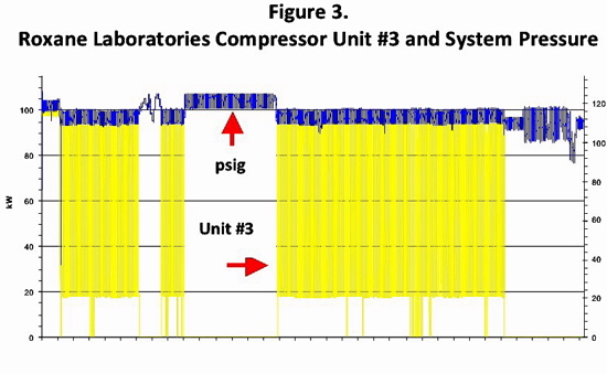
Figure 4
Roxane Laboratories Compressor Units #4 and #5 kW
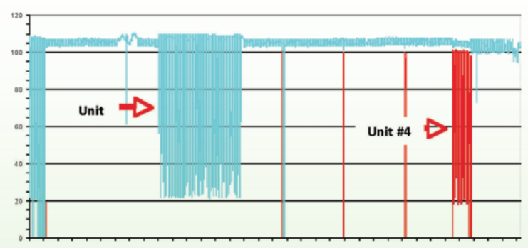
• At any given time, only Unit #5 is on at full load during normal demand
• Unit #5 short cycled as pressure increased with significantly lower demand
• The trim unit #3 continues to short cycle
• A third unit, #4, called on due to falling plant pressure, comes on and goes off immediately
• Regardless of which unit was short cycling, it was only loaded about 30% of the time and operated at about 46% of full load input kW average.
• The net result is 219 full load kW on-line and delivering 448 + (448 x .3) 582 scfm at 110 + (109 x .46) 160.14 input kW or 3.63 scfm/kW.
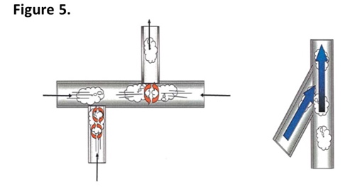
Air Power USA identified the piping size (2”copper) discharge line to a 3” copper header. Although the resistance to flow of copper is less than black iron, the very high velocities (49 fps) in the 3” header trying to handle the load from each compressor, combined with the “crossing tee” configuration (Figure 5) creates very erratic and significant pressure spikes causing the extreme short cycling. This short cycling was a principle cause of the premature airend, motor, and cooler problems.
The other major problem that existed in the air supply was significant condensate carryover past the primary dryers where it had to be handled in a secondary trap area requiring significant maintenance time to successfully protect the production area.
Air Power USA felt the primary problem here again was configuration as the piping going from a 4” copper line in and out of a 1,550-gallon receiver split into two 3” lines going to 550 scfm and 750 scfm rated non-cycling refrigerated dryers. The “crossing tee” where the 550 scfm dryer tried t
o feed into the discharge line from the 750 scfm dryer (see Figure 1), combined with long convoluted piping to the 750 scfm dryer, allowed very little compressed air flow through the 550 scfm dryer, thus often overloading the 750 scfm dryer and raising the pressure dewpoint and pressure loss.
Figure 6.
The Air Power USA audit/review addressed these two very important issues along with other compressed air efficiency projects:
- Size system to be able to handle current 1,200 scfm demand plus an additional 800 scfm for 2,000 scfm at as low a pressure as 105 psig discharge pressure (100 psig system pressure)
- Lower compressors discharge pressure 18 psig for an 8 to 9% improvement in specific power
- Implement compressed air reduction projects (change air motors to electric; repair tagged leaks; replace open blows with venturi amplifier nozzles; reduce system pressure) for a total of 236 scfm about 65-hp or 52 kW
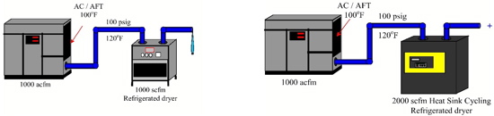
- Replace small non-performing non-cycling refrigerated dryers with a single, oversized, full heat sink type cycling dryer.
Enter the New System
After reviewing the final report, Roxane Laboratories engineering decided to proceed to develop and implement the new ‘world class” compressed air system. Air Power USA was retained to assist the plant engineers in project management with particular attention to the compressors and supporting equipment including the piping material, sizing and configuration. URS Consultants of Columbus, Ohio was the mechanical engineering contractor. Joint meetings were held and following is an abbreviated list of specifications.
System Capability
• All components and total configuration to be sized to efficiently handle 2,000 scfm flow at a discharge pressure as low as 85 psig.
Guidelines for Reconfigured Systems Design Parameters
- All new equipment to be watercooled
- Utilizing the existing air compressors and dryers as much as possible; recommend three different scenarios to reconfigure the system. If new equipment is recommended, identify the energy savings and their pertinent benefits.
- A full networking central control system is required. This should keep all units at full load with one at trim, all others off. Control will limit the number of starts per hour to the proper amount. All units will be controlled automatically with an operating band of ±1-2 psig.
- A monitoring system will also be part of the control system. The exportable critical data will be automatically disseminated.
- Supply system to be redundant to N+1; the loss of any single largest unit to have 100% backup
- Explore benefits of demand side control system with large storage and pressure/flow controller. Evaluate energy savings and positive effects of a constant stable pressure on productivity and quality.
Piping and Compressed Air Treatment
- The piping and compressed air treatment equipment will have characteristics rated at 2,000 scfm at pressures as low as 85 psig; not to exceed 20 fps pipeline velocities
- Interconnecting piping from the compressor discharge to the filter/dryer and from the filter/dryer to create negligible pressure loss
- The coalescing pre-filter shall be sized to handle a flow rate of 2,000 scfm/minimum and still be effective at flows as low as 100 scfm or less. The filter should have a full load pressure loss of 1 psid or less when new and wet. Filter change is due at 3 psid or less. Filter life must exceed 1 year with no particulate filter installed ahead. Manufacturer to state projected life.
- The dryer is to be rated for 2,000 scfm flow rate at 100/100/100. It is to be a full cycling “heat sink” or “thermal mass” type refrigerated compressed air dryer capable of running with the refrigeration system only in direct response to actual heat load. Rated full load pressure loss not to exceed 3 psid.
- Dryer refrigeration compressor starts should be limited to 6 starts per hour based on the size and type of heat sink. The refrigeration compressor will shut off, not just unload. The design should be a “multi-module design” with multiple parallel refrigeration system that can be valved out for repair or adjustment and the dryer can continue to dry the air during that time. This delivers N+1 redundancy without the need of a second or third unit.
The projected near term new demand profile at 105 psig discharge pressure will be:
Full production sustained peak 1,500 scfm 1,818 hours per year
Average full production 1,000 scfm 4,448 hours per year
Weekend and Holidays production 550 scfm 2,496 hours per year
The projected maximum demand over the 5-year expansion will be:
Full production sustained peak 2,000 scfm 1,818 hours per year
Full production average flow 1,500 scfm 4,448 hours per year
Weekends and Holidays 550 scfm 2,496 hours per year
These numbers were generated by the project teams operating model. After the system is fully reconfigured and stabilized, the plant will actively pursue lowering both the discharge (saving input energy) and the system pressure (reducing the flow demand) until they identify the optimum operating system pressure for maximum productivity and quality.
Other Basic System Support Items
Central air management system operating from a single sensing point to hold all units at full load except one at part load, all others off. The operating band to be ±2 psig with a maximum pressure loss from the compressor discharge to the distribution piping entry point of 5 psid
- Dewpoint meter after the dryer
- Flowmeter after the dryer
- Appropriate pressure gauges
- All measurement equipment installed in an appropriate manner for safe removal for service and calibration.
Selecting the Compressed Air Equipment
Working closely with Roxane Laboratories plant engineering and maintenance personnel, a complete matrix was developed with the four leading manufacturers of oil-free, 2-stage, rotary screw compressors. The following is a brief synopsis of the operating energy cost analysis:
- Today’s air-cooled compressors are in relatively poor condition due to normal wear exacerbated by the short cycling and heat; due to the installation piping and lack of proper ventilation; due to the cooling air ducting.
- Projected annual electrical energy cost to run today’s units at the new demand $137,377 per year
- There are two basic ways to approach a new compressed air supply:
- Two large watercooled compressors 250-hp class with backup by the current 125-hp units
- Multiple units to replace the existing five compressors either all at onc
e or one or two at a time
- Running two new 250-hp class units from any of the major manufacturers energy savings compared to running the current equipment at 2,000 scfm demand
- Estimated maximum electrical savings $16,727/year
- Estimated maximum electrical savings $1,654/year
- Running five smaller (150-hp) units compared to the current equipment at 2,000 scfm demand
- Supplying a VSD drive on these oil-free rotary offered very little, if any, energy savings when utilizing the very effective storage created by the piping and receiver
- Main electric drive motors were selected with a .95 motor efficiency in place of the current .93; a 2% gain in specific power or an energy savings of $2,740/year
After considering the other benefits such as these listed below, the team selected the 250-hp size units.
- Fewer machines to maintain
- Less floor space required
- Two units will cover the project start and still have N+1 backup
- At the full demand a third unit of the same size will complete the N+1
- Much simpler, more effective piping.
The New System is Complete
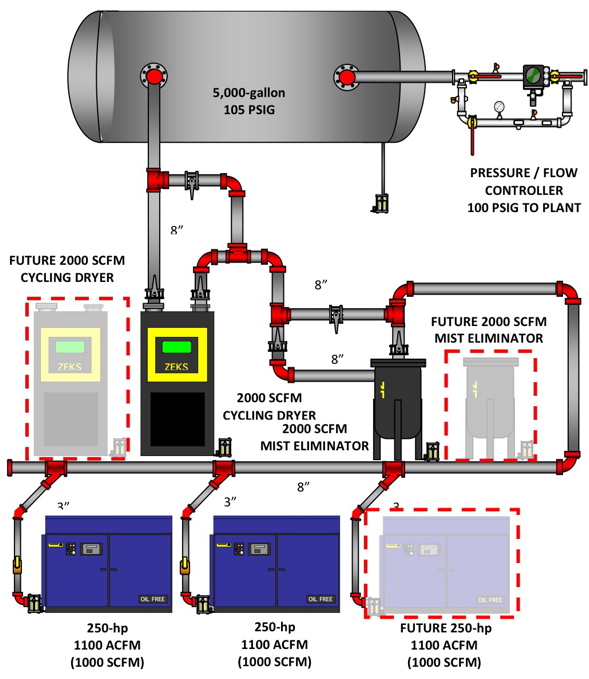
The project team developed the final overall layout and design reflected in Figure 7 in 2004 and implementation was underway. Some key points to observe as shown on this schematic are:
- Discharge line size is now 3” going to an 8” header
- The piping material is stainless steel, which is much more resistant to damage from the highly acidic condensate from an oil-free air compressor than copper or black iron
- Most connections were welded but some were fitted with Victaulic fittings and Viton seals for maximum life and flexibility in the future
- All connections to the header used angled direction entry to avoid high turbulent driven backpressure
- All risers and other drain points have “zero loss” automatic condensate drains
- Room was left for an additional filter, dryer and compressor when the system grows to or exceed 2,000 scfm
- The large storage tank for dry air, before the pressure/flow controller, has compressed air entering the receiver with one line and going to the pressure/flow controller and system with another; the air goes through the receiver.
- The initial pressure settings were discharge pressure of 115 psig – regulated flow to the system, 105 psig
- The project was complete and everything went as planned. Actually, the initial pressure loss in 2004 when the system was set up from the compressor discharge to the pressure flow controller was 1 to 2 psig.
Figure 7.
New Compressed Air System
Where We Are in 2009 – five years into the mission:
- There have been no significant failures or repairs on the primary compressor or dryer/filters
- The filter has not needed changing
- Compressor discharge pressure has been reduced to 125 psig and system pressure to 105 psig
- The growth in demand has not yet reached the 2,000 scfm plateau due to effective plant air management and conservation programs and operating at a lower production distribution header pressure.
However, the second, or trim, unit runs routinely during production which triggers a need for the third compressor to continue the N+1 reliability factor.
- Air Power USA, in conjunction with plant engineering, ran several compressor operating efficiency models comparing a constant speed trim unit to a VSD trim unit. In 2004, the constant speed was slightly lower operating cost than a VSD. In 2009, with the now current data the VSD generated a slightly lower operating cost. In order to achieve this, the VSD would have to be in trim all the time. The plant decided to select a third compressor with the same specification as the two existing units.
Summary
The new “world class” air system has performed as designed with high performance, and extremely high reliabil
ity of all the selected equipment. The system was designed to handle a maximum of 2,200 acfm (2,000 scfm) without any major changes. Today, it is running about 300-500 scfm below that.
If it ever gets to the point where a third unit is needed routinely, it will still perform well but in a diminishing manner. If the growth increases to where the three units have to run together most of the time (2,800 to 3,000 scfm), then consideration will be given to a complete revaluation of the entire supply and demand system as to pipe sizing, storage, regulation of flow, dryer, primary air, etc.
Overall, this story is why it is best to do the audit or review BEFORE you make significant changes or expansions to the air system. A job well done – and still paying off 5 years later.
For more information, please contact Hank Van Ormer, Air Power USA, Tel: 740-862-4112, email: [email protected], www.airpowerusainc.com.
For more articles about pharmaceutical Industry, visit www.airbestpractices.com/industries/pharmaceutical.