One of the components frequently included in a reciprocating air compressor is an air receiver, often referred to as an air tank. Proper air storage is a critical component of intermittent duty cycle because for brief moments, the system can provide more compressed air than would otherwise be provided by the compressor pump. The capacity of compressed air piping also contributes to the total capacity of the air storage system.
Unlike liquid, air is a gas that can be compressed, allowing different volumes of air to occupy a fixed storage space. Capacity is increased with higher storage pressure, the higher pressure squeezes more air molecules into this fixed space, increasing its density. While density impacts pressure, it should be noted that temperature also impacts air pressure. A higher temperature speeds up the movement of air molecules and therefore increases air pressure. Likewise, a lower temperature decreases air pressure.
For purposes of describing air storage, the remainder of the article discusses principles using a constant air temperature. Under constant temperature, the amount of storage capacity is a function of the physical size of the air storage system and the actual measured pressure of the air. Capacity increases when the quantity of air flowing into the storage system is greater than that flowing to the application. Capacity decreases when the air flow used by the application exceeds the quantity being supplied.
Calculating Capacity
Since most US equipment capacity and usage is measured in cubic feet per minute (CFM), it is important to make this measurement consistent in excess capacity of compressed air. CFM is normally defined at standard inlet conditions which would be about 14.7 psi at sea level. Therefore, a comparison of capacity addition relates to that same mass of air, or 14.7 psi. In a compressed air storage tank, adding 14.7 psi of pressure amounts to that same amount of added cubic foot capacity. Likewise, adding 29.4 psi would double the cubic foot capacity and adding 147 psi would increase the cubic foot capacity ten times, etc. The increase is proportional to the percentage increase of the base sea level inlet pressure.
Example: A typical compressor with a 16 cubic foot air receiver (about 120 gallons) plus two cubic feet of pipe capacity might operate with a minimum pressure of 125 psi. Extra capacity is added as the pressure increases. An increase equal to atmospheric pressure (14.7 psi) becomes proportional to the capacity of the air receiver and pipe. Thus, increasing the base pressure above the minimum pressure of 125 psi to 139.7 psi adds 18 cubic feet of capacity to the 18 cubic foot air storage. Likewise, doubling the 14.7 psi increase (29.4 psi) to 154.4 psi would add 36 cubic feet of extra capacity.
|
Tank |
Air Pipe |
Total Storage |
Added Storage |
||
|
Capacity |
Capacity |
Capacity |
Cut in |
Cut out |
Capacity |
|
Cubic Ft |
Cubic Ft |
Cubic Ft |
Pressure |
Pressure |
Cubic Ft |
|
16 |
2 |
18 |
125 |
139.7 |
18 |
|
16 |
2 |
18 |
125 |
154.4 |
36 |
- Gallons / 7.48 = Cubic Feet
- Added Storage = CF * ΔP / 14.7
CF is Cubic Feet of tank + air pipe storage
ΔP = Change of pressure in PSI
14.7 represents atmospheric pressure at sea level
Example 1
- Added Storage = CF * ΔP / 14.7
= 18 * (139.7 – 125) / 14.7
= 18
Example 2
- Added Storage = CF * ΔP / 14.7
= 18 * (154.4 – 125) / 14.7
= 36
|
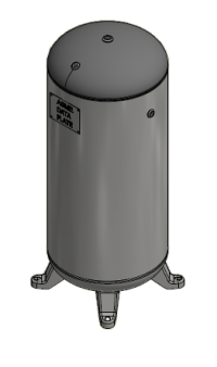
Vertical Air Receiver |
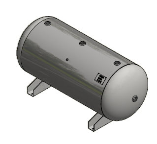
Horizontal Air Receiver |
Applications
Intermittent demand can occur in many commercial applications from automotive repair, small manufacturing, or air bursting. The key ingredient is that while there may be numerous uses of air in small but steady volumes, there tends to be a temporary high-volume use of compressed air that is disproportionally much greater than the normal usage. Such an example might occur in a body shop that blows compressed air into a car to clean it up. The air is used only for a short moment, but also disproportionately uses more compressed air than the other air operated devices. As a result, this application could depend on the capacity of stored air.
In an air bursting application, the use of compressed air might be only for a single purpose, on for only a brief moment, but then could be off for hours or even days. The quick blasts of air are used to start a marine engine or bubble large quantities of water, etc. Since the stored air capacity is needed only occasionally, there is plenty of time for the compressor to restore the air receiver for its next air burst use. In this case, a small compressor might be adequate to operate for hours and pump up a very large air receiver to high pressure.
Using Storage and Capacity to Control the Number of Motor Starts
Air storage also provides balance for start/stop air compressors. Due to the brief starting load placed on an electric motor, it is commonly recommended that the motor start no more than seven times per hour.
In an example using a 16 cubic foot tank (about 120 gallons) plus two cubic feet of pipe capacity, a 35 cfm compressor, average demand of 10 cfm and a pressure range that starts at 125 psi but stops at 150 psi, we can calculate the number of motor starts per hour. Once the compressor reaches its shut off pressure of 150 psi, the differential capacity of compressed air in cubic feet is 18 times 25 psi, divided by 14.7 psi, or 30.6 cubic feet. At a demand rate of 10 cfm, it would take 3.06 minutes to draw the air pressure down to 125 psi.
Added Storage = CF * ΔP / 14.7
= (16 + 2) * (150-125) / 14.7
= 30.6
Drawdown = Added Storage / Demand
= 30.6 / 10
= 3.06 minutes
During the pump-up phase, the rate of increase would be 25 cfm (35 cfm for the compressor less 10 cfm for the demand.) By increasing the 18 cubic feet of storage 25 psi, divided by 14.7 psi and with a 25 cfm pump up rate takes 1.22 minutes.
Added Storage = CF * ΔP / 14.7
= (16 + 2) * (150-125) / 14.7
= 30.6
Pump Up = Added Storage / Rate of Increase
= Added Storage / (Capacity – Demand)
= 30.6 / (35 – 10)
= 1.22 minutes
The combined cycle of 3.06 minutes for drawdown plus the 1.22 minutes of pump up comes to 4.28 minutes, or 14.02 motor starts per hour.
Since the recommended motor start rate is 7 times per hour, an adjustment to the system or operation is needed. One technique would involve adding tank storage capacity. By doubling the tank size to 32 cubic feet plus 2 cubic feet of pipe capacity, the draw down time for the above example would change to 5.78 minutes and the pump-up time would change to 2.31 minutes. The combined cycle time would increase to 8.09 minutes, or 7.42 motor starts per hour.
A second technique to reduce motor starts is increasing the pressure differential. If the pressure range was able to start at 120 psi but stopped at 175 psi, the cycle time more than doubles because its capacity at 18 cubic feet times 55 psi, divided by 14.7 psi, is 67.3 cubic feet, or 6.73 minutes when demand is 10 cfm. Likewise, the pump-up time is 18 cubic feet of storage times 55 psi, divided by 14.7 psi or 2.69 minutes when adding 25 cfm to capacity. The combined cycle time would increase to 9.42 minutes, or 6.37 motor starts per hour. By simply increasing the differential pressure, the compressor runs longer, stays shut off longer, and therefore has fewer motor starts.
A third technique to reduce motor starts is use of a second compressor that alternates with the first compressor. Therefore, in the above example, even though the system incurs 14.02 motor starts per hour, the load on each individual compressor motor is limited to about seven starts per hour.
|
Compressorr |
Demand |
Storage |
Cutoff |
Drawdown |
Cut-in |
Pump up |
Total |
Starts per |
|
Capacity |
Capacity |
Pressure |
Time |
Pressure |
Time |
Cycle Time |
Hour |
|
|
CFM |
CFM |
Cubic Ft |
PSI |
Minutes |
PSI |
Minutes |
Minutes |
|
|
35 |
10 |
18 |
150 |
3.06 |
125 |
1.22 |
4.28 |
14.02 |
|
35 |
10 |
34 |
150 |
5.78 |
125 |
2.31 |
8.09 |
7.42 |
|
35 |
10 |
18 |
175 |
6.73 |
120 |
2.69 |
9.42 |
6.37 |
Location of Compressed Air Storage
Even if storage is in balance to meet the needs of the operation and intermittent capacity, attention still needs to be directed to the location of air storage.In the body shop application where a high volume of air is used to clean and blow out a car, the compressed air must transfer through the air treatment system, piping, distribution point and the air tool. If any of these components have air flow limits below the demand of the application, the stored air that is available in the system may not flow to the application when needed. The symptom is a loss of pressure at the application point even though the pressure is adequate upstream. While it might first appear that the compressor capacity is inadequate, the real issue is distributing the air to where it is needed. One way to solve this constraint is to place part of the compressed air storage near the high use application and ensure the remaining pipe is sized to accommodate the needed flow rate.
Summary
Compressed air storage provides versatile balance in applications where demand is variable. It allows demand to exceed supply on an intermittent basis. It allows a compressor system to balance its starts and stops within the limitations of the electric motor. When storage is properly placed within the air system, it provides a cost-effective method of air filtration and air delivery.
The capacity of air storage is a function of both the physical size of the storage and the amount of pressure exceeding the minimum needs of the system. Proper balance of this storage when combined with appropriate compressor capacity should meet the needs of the application while also enhancing the operation of the air compressor.
The Compressed Air and Gas Institute (CAGI)
The Compressed Air and Gas Institute (CAGI) is the united voice of the compressed air industry, serving as the unbiased authority on technical, educational, promotional, and other matters that affect compressed air and gas equipment suppliers and their customers. CAGI educational resources include e-learning coursework, selection guides, videos and the Compressed Air & Gas Handbook. For the most up-to-date list of Reciprocating Compressor Section members, visit https://cagi.org. |
All photos are courtesy of the Compressed Air and Gas Institute.
To read more Air Compressor Technology articles, visit https://www.airbestpractices.com/technology/air-compressors.
Visit our Webinar Archives to listen to expert presentations on Air Compressor Technology at
https://www.airbestpractices.com/webinars.
Published March 2024 in Compressed Air Best Practices® Magazine