Responsible companies are looking at ways to not only reduce their energy consumption, but to make their production more efficient. This is a great general business practice, but how can you be sure that what you are doing has positively impacted the bottom line? More specifically, what can you implement that is repeatable as a best practice to save energy, and better yet, what can you implement that can be used to retrofit various machines across your floor? One solution is found in upgrading to modern pneumatic valves capable of saving energy by reducing compressed air consumption.
The following is a case study that looks at a specific small component assembler and evaluates how the addition of one component, a new pneumatic valve, can decrease the energy consumption of this assembly cell.
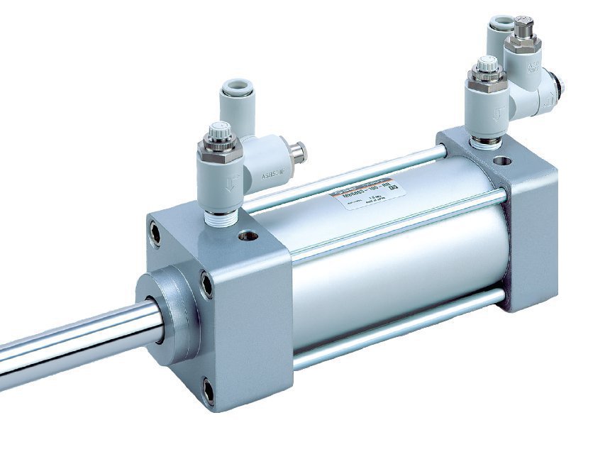
The ASR/ASQ valve components reduce the pressure requirement on the non-working side of a pneumatic cylinder.
Application Example: A Small-Component Assembly Machine
The purpose of this small-component assembly machine is to mechanically fit spacers onto spools. The machine uses a total of ten (10) pneumatic cylinders, working as part of a system to assemble 1,908 finished units per day. The pneumatic cylinders are of various types (rotary, grippers, guided, etc). The machine’s functionality is generally summarized in four steps.
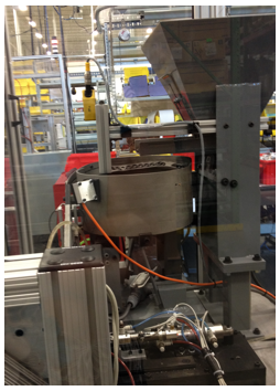
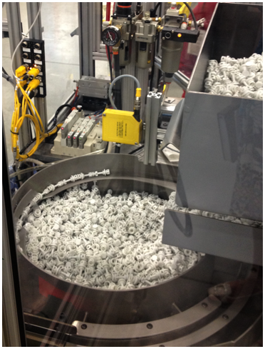
- Step 1: Spacers are placed within a manually filled hopper. The hopper is jolted periodically by a cylinder, moving the spacers to the bottom of the hopper.
- Step 2: The spacers fall into a vibrating bowl feeder where the vibration of the bowl moves the parts to the outside of the feeder channel.
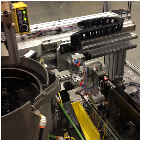
- Step 3: The spacers then fall onto a conveying system where they are mechanically aligned by another series of cylinders.
- Step 4: Finally, the spacers are picked up by a gripper and are positioned for the final phase of the process.
- Step 5: A final system of pneumatic cylinders and valves work together to force the spacer onto the spool.
 |
|
A pneumatic cylinder jolts the hopper periodically, moving the spacers to the bottom of the hopper. |
 |
|
The spacers fall onto a conveying system where they are mechanically aligned by another series of pneumatic cylinders. Meanwhile, a similar process is taking place with the spools. These spools will be what eventually hold the spacers. |
|
 |
|
The final product, spacer on spool, is then ejected into a holding bin where they are now ready for collection. |
The Pneumatic Valve Retrofit
The objective of installing the ASR/ASQ components is to reduce the pressure on the non-working side of a cylinder, and thus reduce the energy consumed annually.
SMC Series ASR/ASQ pneumatic valves were installed on each of the ten (10) cylinders where standard push-to-connect fittings had previously existed. Specifically, one ASR valve was installed on each of the ten cylinder’s non-working side and an ASQ valve was installed on the working side.
The Cylinder’s Low-Pressure/Non-Working Side
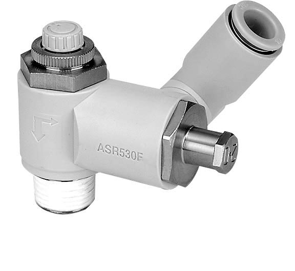
The valves cut air consumption by operating the non-working actuator stroke at a reduced pressure. These valves have the potential to reduce air consumption by up to forty percent. Here is how it works; in conventional installations the working and nonworking stroke operate at the same pressure. The ASR pneumatic valve is installed on the low pressure/non-working side of the cylinder. It contains a regulator, check valve and speed controller providing the low, regulated pressure on the return stroke. Essentially, the ASR is a regulator, check valve, and speed controller all in one.
 |
 |
||||
The ASR contains a regulator, check valve and speed controller and is installed on the low pressure/non-working side of the cylinder.
|
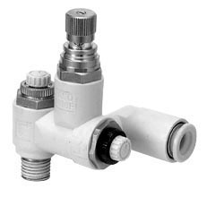
The ASQ contains an exhaust valve with a speed controller and is installed on the cylinder’s high-pressure/working side. |
The Cylinder’s High-Pressure/Working Side
On the working/high pressure side, the ASQ is installed. The ASQ contains an exhaust valve with a speed controller. The ASQ exhausts the supply pressure on the return stroke.
The quick exhaust cuts air consumption by reducing the pressure on the non-working stroke. The inclusion of the speed controllers make the movement more smooth - and the inclusion of the quick exhaust make the response time faster. If just a flow control is used, then the pressure rise is delayed, slowing the response time - meaning a longer stop time.
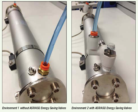
Lab Test on Reduced Flow RequirementsTo determine the exact savings, a test environment was created in the SMC lab to quantify the exact savings. Environment 1 was first connected to a 6.4 gallon tank of compressed air at a pressure of 85 psig. There was six feet of tubing to a regulator set at 45 psi. Once the cylinder was connected and the compressed air tank was filled, the air compressor was turned off. This provided a measurable quantity of air. The actuator was then supplied the air and thus, began to actuate. In this environment, 47 strokes depleted the static air supply. The process was repeated three times to ensure consistency, and consistently 47 strokes depleted the supply. Environment 2 was then connected to the same system. The only variable in the environment was the introduction of the energy saving valves to the cylinder. The standard push-to-connect fittings were removed from both sides of the cylinder and the ASR/ASQ valves were added in their place. Under the same conditions, 54 strokes depleted the static air supply. This is an increase of 7 strokes from Environment 1. The addition of the energy saving valves showed a 19% increase in the number of strokes, or quantity of work, possible from the static supply of air, and thus a 19% decrease in air consumption. The added plus is that in environment 2, the pressure was set at 45psi. In short, the ASQ is a pilot valve and 2-way flow control valve all in one.
|
Return-on-Investment
The small-component assembly machine potentially saw a nineteen percent decrease in air consumption after the energy saving valves were installed on all ten cylinders. Plans are in place to confirm these numbers with compressed air flow data-logging.
The estimated annual compressed air cost per cylinder in the system was \$1,177 per year. With ten like cylinders, the total annual cost to run the machine was \$11,776. After installation of the series ASR/ASQ valves, the operating cost of these ten cylinders could fall below \$9,539 – a decrease in energy costs of nineteen percent. Considering the list price of each of the valves is approximately \$27, the return on investment is clear.
Note: all compressed air savings calculations assume that the compressor controls are dynamic and the power consumption ratio to operating capacity ratio is a 1:1. If using a compressor without dynamic controls, the compressor will need to be adjusted to benefit from the full energy savings expressed in this example.
For more information contact Andy Thedjoprasetyono, Head of Product Management, SMC Corporation of America, tel: 317-688-0164, email: [email protected].
To read more System Assessment articles, please click here.