Compressed air users looking for energy reduction often identify their air compressors as a prime area for savings potential. But …what about end uses? As attendees of the CAC’s Fundamentals of Compressed Air seminars learn, there are a large number of obvious measures that can be implemented, such as leakage reduction, reducing open blowing and eliminating inappropriate uses..however, there are other more technical opportunities available that involve properly specifying or redesigning existing pneumatic circuitry in compressed air operated machines and processes.
"In the past, energy was relatively cheap thus only the initial project cost received much consideration in machine design”, says Jeff Yarnall, a Technical Service Provider for BPA and a CAC Advanced level instructor, “If pneumatics could perform a task, automation machinery was designed around using compressed air rather than hydraulics, direct electro-mechanical action, or even hiring a person to do the job. As labor became more expensive, automation and machinery have taken the place of boring, repetitive and sometimes dangerous work.
Fast forward to the present … energy costs now represent approximately 75% of the total cost of running a compressed air system. The CAC for the past 12 years has been training plant engineers, maintenance managers, operators, and plant managers that energy costs should now be the driving force behind compressed air decisions. Most have embraced these concepts and have upgraded their supply side to reduce costs. We are now entering the next phase of cost reduction - use compressed air appropriately or switch to another more efficient source of energy. Because of rising energy costs the time is right to look into demand side savings."
BC Hydro, a Compressed Air Challenge Sponsor, has recognized this potential for years as part of their Compressed Air Initiative and encourages customers to reexamine the way their compressed air powered actuators use energy. The following is an adaptation of a BC Hydro publication “Saving Energy through Compressed Air Systems”:
Compressed air is widely used in industry today. Although it may be performing adequately, it's well worth taking a closer look at the system to improve operating efficiency, since potential savings could add up to thousands of dollars in operating costs and result in significantly reduced greenhouse gas emissions every year.
A key question that should be considered is: "In a particular application, does compressed air have operational and process advantages that would warrant the use of compressed air over other methods of lower-cost electrical energy conversion?"
Alternative power systems
The three most commonly used power conversion systems in industry are electro-mechanical, hydraulic and compressed air. Each has good applications, but compressed air always uses the most energy. Figure 1 illustrates an object required to be pushed off a roll case with a force of 2,830 pounds at a speed of 1.5 feet per second. The theoretical horsepower to perform this work is 7.72 hp with no efficiency loss.


Energy loss sources and areas for saving
Excessive pressures-pressure reduction
The system operating pressure varies from one industry to another. In the sawmilling industry a large number of compressors typically run at 105 to115 psig. On the other hand, pulp mills often run their compressors at 90 psig. Some secondary manufacturing industries run as low as 70 to 80 psig. The system pressure should not be any higher than is functionally necessary, since the greater the pressure the higher the energy cost to produce the increased pressure. As the pressure increases, a factor called the compression ratio (CR) increases, as demonstrated in the following formula:

A rule of thumb used for single stage positive displacement rotary screw compressors is that for every 1 psi change in compressor outlet pressure, there is a corresponding 0.5% change in energy requirements to produce the compressed air.
Once the system pressure is established, further reductions in pressure can be made at individual actuators where full system pressure is not required. For example, consider an application as shown in Figure 2 where a work piece is being swept off a roll case. For the following formula, assume that the pressure required to perform the work is 60 psi, and use the data contained in Table 2.
scfm = cylinder volume x cycle x compression ratio
Where:
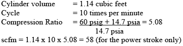

Figure 2 – Kicker Example (Source: BC Hydro)

Dual pressurization of air cylinders
Another option for power savings without any production losses is that of dual pressurization. Dual pressurization becomes a valid means of energy savings when an air cylinder/actuator needs full pressure in one direction only, and can return with minimal pressure. In this concept, high-pressure plant air (or air regulated to required pressure) is put into the extension end of the cylinder to move the heavy load, and on the return stroke a lower pressure is used. Table 3 on the following page shows the magnitude of energy losses in over-pressuring the return stroke of a cylinder.

Utilization of single-acting cylinders
Another energy-saving option is to consider single acting cylinders with gravity or spring return in places where high-pressure air is required only in one direction. On the return stroke, either gravity or a spring may be used to return the cylinder to its original position. This would result in significant energy savings as shown in Table 4.

Figure 3 – Example of Spring Return (Source: BC Hydro)

Designing to minimize pressure drop
Excess pressure drop in a system can add up to hundreds of dollars in energy loss each year. Whenever a fluid flows through an object, there are losses: the more air you try to push through, the more resistance there is to flow. The more resistance, the more force or pressure is required to move the air. The pressure used to overcome this resistance is referred to as pressure drop. Energy savings can be achieved with proper design and selection of air components and distribution piping.
Say, for example, the pressure drop for a 500 hp compressed air system is reduced 2 psi. Energy cost savings could be: 500 hp x .746 kW per hp x 6,000 hours per year x l.0% x 10¢ per kWh = \$2,238 per year.
Directional control valves
Directional control valves are used to start, stop, or change direction of flow in compressed air applications. A wide variety of these valves are used by industry. Control valves are designed for different applications. Once a suitable type is selected, then the flow capacity of the valve must be matched to the application. The flow capacities of directional control valves are rated by a flow coefficient (Cv). As the Cv increases the pressure drop decreases while maintaining the same flow and final pressure parameters. Therefore, careful consideration should be given to Cv values when selecting valves. See CAC’s Best Practice for Compressed Air Systems book for more information.
Filter regulator lubricators (FRLs)
FRLs are secondary air preparation components located just before the actuator, and sometimes referred to as the air station. This part of an air system must not be taken for granted or ignored because it must do the required function properly and it must do it as efficiently as possible. The proper design and selection of the secondary preparation system is essential to minimize the efficiency loss/pressure drop through it. If pressure drop is ignored, an FRL station can have a pressure drop in excess of 10 psi, which translates to an extra energy requirement of 5%. A recommended pressure drop to work towards is 2 psi.
Distribution piping
A poorly designed compressed air distribution system produces low pressure at the actuators, insufficient compressor capacity and lack of air flow. The more pressure drop there is in a distribution system, the higher the compressor pressure setting must be in order to provide the required pressure at the end use. The higher the pressure at which the compressor must operate, the higher the power required to generate the compressed air.
Leaks
Experienced compressed air auditors find that most of the leaks and pressure losses in a system are in the final end uses (valves, fittings, hoses etc). These waste energy, but can also negatively affect the performance of the pneumatic process through lower power stroke, slower operation speed and inconsistent operation. Monitoring of important processes can reveal when problems are occurring. A baseline for the air requirement, flow, pressure and even temperature, can be established when the system is relatively free from leaks, when no unnecessary air is being used, and production is at normal levels. With this baseline, the air system can be monitored over a set period of time under normal conditions, and a control chart or history can be developed. This provides a picture of what normal operating conditions look like and can trigger action when required.
”Many times compressed air users focus their attention on the air compressor as the problem when the air pressure they require isn’t adequate for their demand side process equipment needs, explains Roger Antonioli, Senior Account Manager for Scales Air Compressor Corporation and a CAC Fundamentals instructor. However, too often the problem lies instead in their air distribution piping system. Some common issues revolve around systems that were inadequately sized or designed initially, or ones which were sized initially for an earlier air flow requirement that has now since grown to a different profile of air usage demand. There are also many piping systems which have been allowed to deteriorate without proper attention and repair, and those that were designed with little thought of appropriate storage requirements to accommodate demand side process operations. Compressed air system owners and operators need to realize that poorly designed air distribution systems may cost less initially to purchase and install, but the life cycle costs of poorly designed air distribution systems will far exceed their initial purchase and installation cost savings.”
A further discussion of pneumatic system optimization appears in CAC’s “Best Practices for Compressed Air Systems” Appendix 4 (This 325 page manual is available at the CAC bookstore).
For more information please contact: Jeff Yarnall, PE, Phone: (503).639.0808 [email protected], or Roger Antonioli, Phone: (610) 522-8480 [email protected].