High Flow ‘On-demand’ Controls for Sandblasting Saves Energy Over Traditional Control
Introduction
Most industrial systems like compressed air have essentially random demand if you look at the long-term life cycle of the system. Hundreds, even thousands of independent small and large subsystems require constant or varying flow. These demands are typically not timed or synchronized with each other, so they aggregate to a fairly random flow profile, within a range. That range changes significantly when production processes change. Certainly a 2-week audit might show some patterns that appear predictable for demand A (“production”) and demand B (“non-production”) or day type, but they change over time as the plant adapts to new production systems and removes old ones. If demand was that profile forever, a lesser experienced auditor might be tempted to size one set of compressors that work perfectly for that profile but not for alternates.
Thus, typical industrial compressed air systems should be designed for the full range of flow, plus growth, with all flow changes and ranges possible, at one constant pressure, not just the flow ranges and changes seen in one 2-week audit. This usually results in a multiplex system of some type, typically with similar size and type compressors that are rotated and staged by an automation system. In the cases where VFD or centrifugal compressors are included, special design criteria exist (see previous ABP articles on “Screw Compressor Control Gap”, “Centrifugal Compressor Control Gap” and “VFD and Master Controls”).
In some general compressed air systems, one dominant process “shocks” the system, creating a peak that is 2X or more of the normal peak, special design criteria will make the above system less than ideal. It could be transport air in a materials processing company, test air in a microelectronics fab system, or sandblasting in large metal fabrication. In the case of large sandblasting systems, the peak can be well over 10X the non-sandblasting demand. In this article, I will discuss a real system that has a 34:1 peak to average, and how to save 70% energy even beyond “best practices” with a VFD compressor. There is no VFD compressor on the market that can flow that range! A different type of system design is needed for these large sandblasting systems.
System Description
In the heavy fabrication business, large weldments are created for structures so large that they can only be transported by barge, so they are located at port facilities. These huge fabrication shops build or repair large boats or structural weldments for permanent structures. In this example, the final product is a bridge structure over 100 ft long by 30 ft long weighing more than 10 tons. Before welding, the large pieces need to be sandblasted. Sometimes they are blasted afterwards also. Huge sandblasting areas which the workers work inside of are built, and dedicated sandblasting “pots” are designed and installed. In order to blast a larger surface area in a time-efficient manner, the nozzles used for these types of systems are often quite large, sometimes more than 0.50” diameter. The system we are looking at in this article had four large nozzles. At the time of the audit, 0.625” nozzles with air flow demands of about 500 scfm each were tested. These were the largest ones in inventory. See Figures 1. At the time of the photo, small sandblasting was occurring, using a much smaller pot and nozzles.
Figure 1. Sandblasting Pot
Since the large pot was designed for four 500 scfm nozzles, 2,000 scfm peak, a 2,900 scfm compressed air system was matched to it. That same system provides general air for small demands such as maintenance and the dust collector. The system had the best-available efficiency compressors, 2-stage oil-lubricated screw with a VFD. However, it was designed for peak, not the off-peak times. The largest available unit from the local supplier was rated for 1450 scfm, so two units were installed, one with a VFD and the other fixed speed. They were plumbed to a 3,250 scfm cycling refrigerated dryer and mist eliminator. See Figure 4 for a system diagram.
In a nearby light manufacturing building, a 50 hp load-unload compressor with dryer is installed. The compressor was very lightly loaded. See Table 1 for a summary of equipment and Figure 2 for a system diagram.
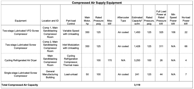
Table 1. Equipment Inventory. Click to enlarge.
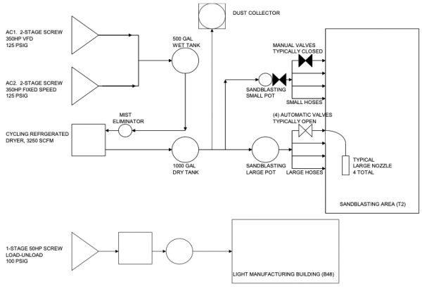
Figure 2. Existing System Diagram
Data Collection and Analysis
At the beginning of the audit, it was not clear how often the large sandblasting would occur, if at all. Production orders for larger fabrication items was less at the time. The small pot was being used most of the time, however. Since a preliminary measure was to use an on-demand control system with a smaller compressor running most of the time, and there already was a smaller system nearby that might be integrated, we monitored both systems at the same time. The following data collection, together with testing was done:
2 week Data Collection, 8-second sample rate:
- AC1 (VFD) power
- AC1 (VFD) inlet pressure
- AC2 (fixed speed) current
- AC2 (fixed speed) inlet pressure
- Sandblasting system pressure
- 50 hp power
- 50 hp system pressure
One-time tests:
- Ran fixed speed unit, AC2, in “hand” (inlet modulated) at first. This gave a stable flow metric (in modulation).
- Ran VFD, AC1, if demand was high enough to keep it in speed range.
- Opened one large nozzle at a time, while datalogging.
The trend data showed that the large pot was used only four times in two weeks, a total of 1.8 hours, or only 1.1% of the time! The small pot was used only 14 hours, only 8.4% of the time. The system was pressurized 49.5 hours/week, 29.5% of the time. A large VFD compressor was running at min speed and loading. Although the large compressor is fairly efficient in its speed range, it is not at the low end, requiring an average of 32 kW to supply 42 scfm of mostly leaks. If the primary compressor was not a VFD, it would be far worse, about 200 kW at that load. Trend data also showed that the large nozzles leaked, and were not de-pressurized automatically. See Figures 3 to 4 for a summary. “T2” is the name of the large sandblasting system.
The general manufacturing system was also very lightly loaded, with no large peaks. Its compressor had a much lower no-load power, only 7 kW, however. “B48” is the name of the general manufacturing system building.
The existing system performance is as follows:
- Average total flow: 66 scfm
- Peak total flow: 2290 scfm
- Total hours/yr: 5,296
- Average pressure: 131 psig for sandblasting and 103 psig for general air
- Total average power: 37 kW
- Efficiency: 1.79 scfm/kW (55.9 kW/100 scfm)
- Energy usage: 196,668 kWh/yr
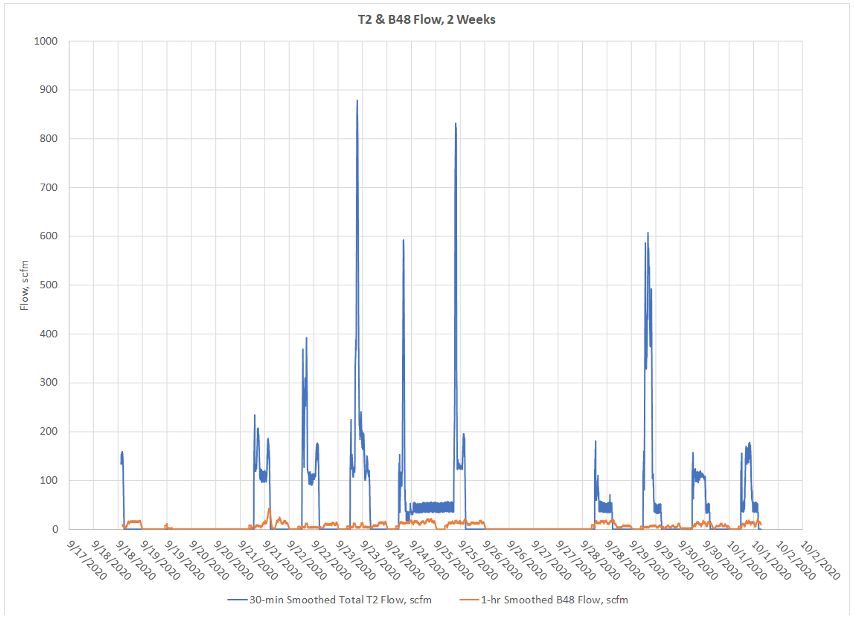
Figure 3. Flow, 2 Weeks. Cick to enlarge.
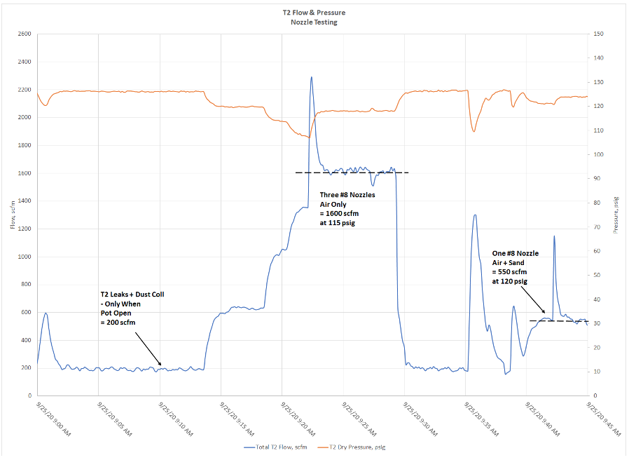
Figure 4. Flow and Pressure, Peak Flow Test. Click to enlarge.
Recommended Improvements
Somehow, the large compressor has to be shut off somehow during non-peak periods. This seems simple, but it is not. Operators would not be allowed to randomly start and stop a large system like this. It has to serve other needs, and operations usually does not have the authority to start and stop compressors anyway. The system has to be automatic and reliable.
A conventional control system with adding compressors as demand increases and removing them as it decreases would not work well with these sized compressors, even if T2 and B48 were integrated. The small compressor could be put in position 1, but then the large compressor would end up being “bumped” often for small peaks, and starting and stopping too often. What it needed is an “on-demand” automation system that accomplishes the following functions:
- Use a very reliable indicator of peak demand. This is best done with the safety electrical switches on the nozzles, not flow or pressure. These electrical switches are part of the larger nozzle systems, right on the handle of the nozzle. When the first automatic nozzle switch depressed, large sandblasting has started. After the last one has been opened, it would indicate that large sandblasting is over.
- Minimize dead load by automatic valves when no peak is occurring
- Run the small compressor load-unload when no peak is occurring
- Run only the larger compressor (or compressors) when the peak is occurring. And run them in the right mode, the VFD in trim at all loads.
This is a custom control system. To the best of our knowledge, no compressed air OEM or automation company offers a standard sandblasting on-demand control like this. However, this could be a system design that could adapt to many different configurations of sandblasting systems. That is why we think this article is necessary.
The specific elements of this project that would accomplish the above functions are as follows (see Figure 5):
- Install a 2” pipe between the B48 and T2 systems.
- Install valves to run parts of system at lower pressure and isolate leaky sandblasting hoses during non-use:
- Install a pressure regulating valve for B48, set at 100 psig
- Install pressure regulator for the T2 dust collectors, set at 100 psig
- Install four reliable normally-closed electrical solenoid valves for large pot lines, one per large nozzle.
- Install one solenoid valve for the small pot compressed air supply
- Upgrade the B48 compressor for 125 psig, as follows:
- Purchase new motor: 60 hp 1800 rpm ODP 3/60/460V 364TSC (C-flange) frame
- Upgrade B48 and T2 compressors for remote control, as follows:
- Remote set point of VFD.
- Remote load and start.
- Install a custom automation system, as follows:
- Industry-standard PLC with a display in the T2 compressor room.
- Install remote I-O at B48 & T2, with relays for load and start.
- Install pressure transmitter in T2 (high pressure).
- Adjust local modulation for all three compressors to 130 psig
- Wire large sandblasting nozzle electrical switches through relays to the automation system, so it knows when each nozzle is being used by an operator. The first one to close would put the system into “large sandblasting” mode, and after the last one is open and a timer expires, it would go back to “off peak” mode.
- Install 1-hr timed start button for small pot air.
- Wire small and large sandblasting pot solenoid valves to PLC.
- Isolate sandblasting hoses when not in use by closing the solenoid valves automatically.
- Stage compressors differently based on whether the system is in “large sandblasting” of “off-peak” mode.
- Tune and commission the system in all modes and transitions.
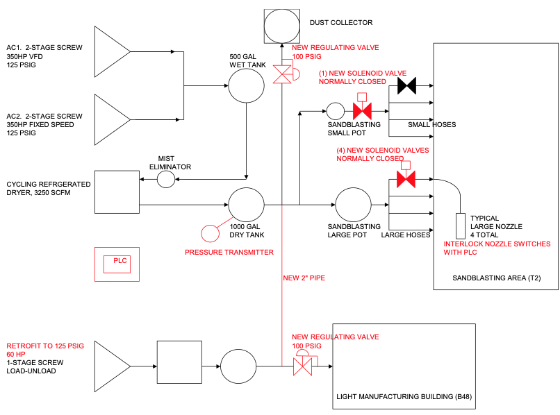
Figure 5. Recommended Improved System Diagram. Click to enlarge.
Energy Savings
The improved system performance is as follows:
- Average total flow: 12 scfm
- Peak total flow: 2290 scfm
- Total hours/yr: 4,505
- Average pressure: 128 psig for sandblasting and general air (before regulators)
- Total average power: 12 kW
- Efficiency: 4.37 scfm/kW (22.9 kW/100 scfm)
- Energy usage: 23,365 kWh/yr
- Savings: 173,303 kWh/yr
Savings are 85%! In this system, total energy cost was about \$9,200/yr. They only paid \$0.047/kWh (Washington, large industrial). But the above project which required no new compressors could save about 85% of the energy, \$7,800/yr, plus about \$5,000 in maintenance, \$12,820/yr total. The project cost could be as high as \$75,000, doing it all right. With incentives, the payback was reduced to about 3 years. But remember that this system already had a VFD compressor, and only operates 2,500 hours per year. For other systems that are not VFD-driven now, that operate longer, and have higher energy costs, the payback could be lower than 2 years even without an incentive.
Conclusions
An “on-demand” system that switches between two different modes is needed to optimize high peak sandblasting systems. By operating a small compressor with low no-load power during non-peak times and the optimal large compressors only when sandblasting is occurring, significant savings can be had. If a large VFD compressor is currently being used, this system will save lots of energy and reduce running hours, lowering maintenance and operating the compressor in its more reliable range.
To read similar System Assessment articles visit www.airbestpractices.com/system-assessments.


