Introduction
This article presents a case study of Grimmway Farms; a carrot growing and packing firm located in California’s Central Valley that was able to improve its compressed air system efficiency after implementing system automation and making relatively small equipment and piping changes.
 Grimmway Farms uses compressed air for the production and clean-up processes in their carrot packing plants. After having been approached by the Ecos Air Program (see sidebar), members of Grimmway’s energy efficiency program realized that in addition to decreasing the continued energy use of their compressed air system while simultaneously improving overall performance, there may also be an opportunity to receive a considerable monetary incentive which could offset the cost of the suggested energy reduction improvements.
 |
System Assessment |
|---|---|
| Where: | Arvin, CA |
| Industry: | Food Processing |
| Issues: | Multiple compressors are not automated and are therefore inefficient |
| Audit Type: | Compressed Air System |
| System Assessment Win/Win Results* | |
|---|---|
| Reduction in Energy Use: | 765,274 kWh |
| Reduction in CO2 Emissions: | 545 metric tons |
| Equivalent CO2 for homes: | 72 homes |
| Equivalent CO2 for vehicles: | 100 vehicles |
| Approximate Annual Savings: | $64,283 |
| Investment | $120,000 |
| Energy Rebate | $65,428 |
| Simple ROI | 11 months |
*Annual energy consumption
Ecos Air worked with auditor Kyle Harris, a Department of Energy “Compressed Air System Energy Expert”, to perform the assessment of the existing compressed air system and who was a major contributor to this article.
System Before Assessment
The pre-project system, sited in two buildings (D and A1) with normally closed interconnected piping, operated independently and consisted of 1x 200 hp, 5 x 150 hp and 1 –x 100 hp (not in operation) oil-flooded, variable displacement controlled, rotary screw air compressors. An additional new 200 hp air compressor had been previously purchased for the facility but had not been installed.
|
Compressor System before Assesment | Compressor System after Assesment | |
|---|---|---|---|
| Operating hours: | 8736 hours | 8736 hours | |
| Power Cost kW/h | $0.084 | $0.084 | |
| Avg. Air Flow | 1903 acfm | 1782 acfm | |
| Plant Air Pressure | 100 psig controlled to 85 psig and 32 psig |
100 psig controlled to 83 psig and 32 psig |
|
| Compressed Air Specific Power | 21.7 kW/100 cfm | 18.2 kW/100 cfm | |
| Annual Energy | 3,596,788 kWh | 2,831,338 | |
| Annual Energy Cost | $302,130 | $237,822 | |
Local controls for each of the Building D air compressors maintained a system pressure of 97 - 99 psig with full flow at 97 psig and no flow at approximately 102 psig. If unloaded for 10 minutes, the compressors would automatically shut down until system pressure reached 90 psig at which time they would restart. These air compressors discharged into a common 1,020 gallon air receiver before entering one of two refrigerated air dryers or a desiccant filled blower purge air dryer. Compressed air from the blower purge air dryer discharged into a 3,000 gallon air receiver and then through a flow controller/demand expander which was set at 83 psig. After exiting the refrigerated air dryers, the compressed air entered a separate 3,000 gallon receiver and discharged through one of two flow controller/demand expanders. One flow controller was set at 83 psig while the second was set at 32 psig for a specific process in the plant. At the time of the assessment, the normally closed crossover valve between the discharge of the refrigerated compressed air dryers and the desiccant blower purge air dryer was found to be open.
Building A1’s compressor controls operated similarly, except system pressure was maintained at 106 - 108 psig with full flow at 106 psig and no flow at approximately 114 psig. They too would automatically shut down if unloaded for 10 minutes but would restart at approximately 95 psig. These air compressors discharged into a common 1,020 gallon air receiver where the air entered a single refrigerated air dryer. The compressed air was then controlled by a flow controller/demand expander to a set point of 87 psig.
 |
 |
| Incentive Details Grimmway Farms received a substantial rebate of \$65,482 (55% of the total project cost) from Pacific Gas & Electric's Ecos Air Program. This innovative program works with industrial facilities on behalf of a utility to search for users of compressed air, coordinate walkthroughs and site audits, manage all applications and forms, establish flow and kW baseline parameters, develop a finacial summary with payback and verify final conditions to ensure that the savings claimed by the utility are genuine and verifiable when reporting to their utility commission. While there are many utilities that provide kWh reduction incentives for customers that implement efficiency measures, the process is normally administered by either the customers themselves or by the equipment vendor. Alternatively, the Ecos Air PRogram has been developed for utilities willing to fund a vendor-neutral third-party contractor to implement an efficiency program for industrial system compressed air users. In this case, the utility simply establishes a financial budget and leaves program execution to Ecos Air. |
|
Baseline Determination
Data collection took place over a 7 day period during which plant personnel indicated that the plant was operating in a typical fashion. Compressor power and system pressure were collected via data loggers and data storage equipment, analyzed in LogTool v2 and then imported into AIRMaster+ v1.2 where various scenarios were modeled. Estimated annual energy consumption was extrapolated from the study period to a full year.
According to plant personnel, the Grimmway Farms air compressor system remains pressurized 24 hours per day, 7 days per week. Therefore, the number of annual hours used for all calculations was 8,736 which assumed one day of complete plant shutdown. The annual energy cost to operate only the compressors was calculated at the usage rate of \$0.084 per kWh. Table 1 and Figure 2 illustrate the data collection findings.
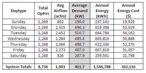
Table 1 - Baseline System Profits
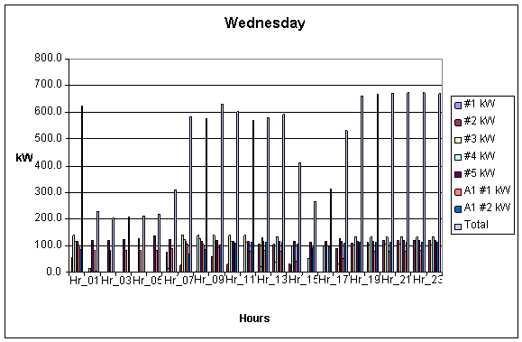
Figure 2 - Typical Day Profile
Issues with the System
Common to multiple compressor facilities without automated control systems or interconnected piping, the Grimmway Farms compressed air system was not optimally matching compressor output to system demand. Data collection proved this to be the case and multiple compressors were found to be operating partially loaded and therefore not running at their maximum efficiency. The goal is to always have “base” compressors running at full load with “trim” units responding to swings in demand rather than operating two or more compressors at part load. Additionally, connecting the two separate compressed air systems would allow both loops to be supported by compressors in either building. The major modifications recommended were as follows:
- Automate the entire air compressor system
- Open the 3” and 4” headers connecting Buildings D and A1 to allow the compressed air to feed either building
- Install the new 200 hp and remove the 100 hp (unused) compressor
- Install a new refrigerated air dryer, flow controller, 3 flow meters and a dew point meter for the lowest dew point process
- Lower overall system pressure
System After Assessment and Upgrades
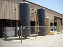
The customer chose to use Accurate Air Engineering, Inc. to implement the above system improvement measures. Figure 3 is a simplified illustration of the post-project system.
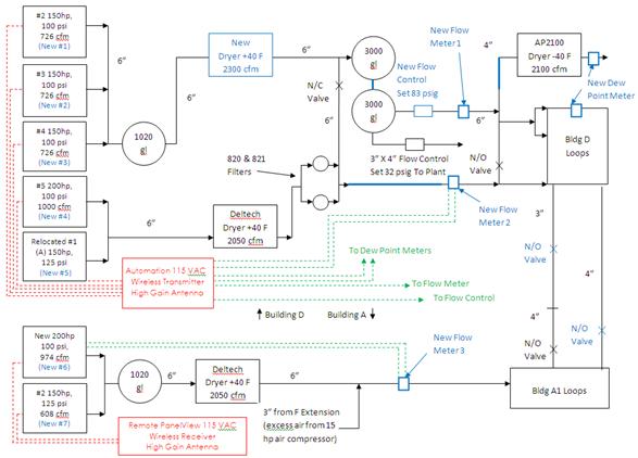
Figure 3 - Malaga Layout with Automation
 The original compressor #1 (100 hp) in Building D was removed as well as the flow controller in Building A1. The new 200 hp compressor was installed in Building A in place of one of the 150 hp compressors which was relocated into Building D. A central Gardner Denver control system was installed to automate all compressors in the system. This control system enables the compressors to operate within a narrow dead-band and at a lower pressure using a “Base Load and Trim” strategy. Compressors are now initiated only when needed in a fixed (last-in/first-out) order sequence. For convenience, the compressors were renumbered (Table 2).
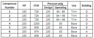
Table 2 - Summary of Compressor Ratings, Location and Use
The combined system’s “trim” station includes compressors #1, #2, and #3 which now operate from 84 – 98 pisg (rather than 98 psig). They discharge into the 1020 gallon wet receiver before entering into a new refrigerated air dryer. Next, the air enters the combined 3000 gallon dry receivers (the GD air dryer was removed and the two 3000 gallon receivers connected) before flowing through a new 3,200 cfm flow controller/demand expander set at 83 psig ± 1 psig which is maintained with a full PID digital control loop connected to the automation panel.
Building D’s “base” compressors #4 and #5 connect to the main supply header downstream of the new “trim” flow controller. Building A’s compressors #6 and #7 are also part of the “base” station and now feed both Building D and Building A. All “base” compressors which originally operated from 98 to 107 psig now operate 100% loaded at 83 psig. This is due to the fact that they are piped in downstream of the new Building D flow controller which forces them to operate 100% loaded at a pressure that is lower than their design, and allows them to deliver the same flow using less power.
|
| "As a result of the above changes to Grimmway Farm's compressed air system, compressor output more closely matches system demand, and continued energy costs have been reduced by approximately \$64,000 annually." -Patricia Boyd, Ecos Air |
Control Scheme
To determine “trim” compressor loading, rate-of-change pressure is calculated and monitored at the two trim station 3,000 gallon air receivers. “Base” compressor loading is determined by downstream pressure in the plant.
From a zero flow point and compressed air demand rising, the #1 (150 hp) “trim” compressor starts and runs load/no-load until fully loaded. When system demand exceeds the capacity of the #1 air compressor (rate of decay in 3,000 x 2 gallons = negative) the #3 (150 hp) “trim” air compressor will start and run load/no-load until it too is fully loaded. When system demand exceeds the capacity of the #1 and #3 (300 hp total) compressors, the #7 (150 hp) “base” compressor will start. The #1 and #3 air compressors will respond by unloading until the demand exceeds the new #7 air compressor. As load again increases, the “trim” compressors begin to load as described in the steps listed previously.
When the demand exceeds the capacity of the #1, #3 and #7 compressors (450 hp total), the #4 (200 hp) “trim” compressor initiates. Again, the steps listed above for the “trim” air compressors will repeat and any additional demand will initiate the #5 (150 hp) compressor and finally the #6 (200 hp) air compressor. The #2 (150 hp) “trim” air compressor will start if another “trim” compressor were to fail, any other air compressor failed and the demand was greater than the output of the operating air compressor(s), or the demand exceeds the capacity of all other air compressors.
“Base” compressors drop out when the demand expander is 100% closed, “trim” compressors are unloaded and the system pressure rises to 1.5 psig above the demand expander set-point, or 84.5 psig.
Post Monitoring Results
Post monitoring results (Table 3 and Figure 4) were collected on the new automation system and downloaded to a computer for analysis and monitoring.
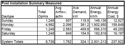
Table 3 - Post Monitoring Results
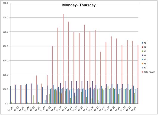
Figure 4 - Typical Post System Day Profile
Conclusion
As a result of the above changes to Grimmway Farm’s compressed air system, compressor output more closely matches system demand and continued energy costs have been reduced by approximately \$64,000 annually. Additionally, a rebate of over \$65,000 was received which lowered the project cost by 55%.
Energy Savings Summary Calculation
3,596,788 kWh – 2,831,388 kWh = 765,400 kWh
Annual Cost Savings Calculation
$302,130 – $237,822 = $64,308
For more information please visit Ecos Air, and Accurate Air Engineering, Inc.