Introduction
It is becoming a “best practice” to install a variable frequency drive (VFD) air compressor whenever one is replacing an old air compressor. As a result, real systems have fixed-speed and VFD air compressors, mixed. I have observed several VFD compressor sizing methods. In my last article, I referred to a common method: size one VFD compressor for the whole system. This can work. However, if it doesn’t meet a higher peak demand, one or more of the old compressors will be started, and a mixed system results. Another method is to replace a compressor with the same size, but with a VFD. If the compressor that was replaced is large, a big VFD is installed. If small, a small one. Yet another method is to segment the system. In all these cases, there is a VFD compressor in a system that has not been really designed. It just happened. Many of these systems aren’t operating efficiently or reliably, because system issues and VFD compressor sizing wasn’t well thought out.
The goal of this article is to give some pointers for selecting and installing the right size VFD air compressor in a multiple compressor system.
Summary
In a nutshell, I recommend the following when a VFD air compressor is added to a multiple-compressor system:
- Develop a Solid Flow Profile
- Determine Flow Ranges for “Trim” Air Compressor(s)
- Size VFD & Base-load Air Compressor(s) From Variance & Base-load Size(s)
Develop a Solid Flow Profile
When you have multiple air compressors, developing a flow profile might be easier said than done, particularly if there are multiple air compressor stations. Installing one permanent flow meter at the outlet of each compressor station’s dryers is the preferable method. They can be easily hot-tapped. Several manufacturers make thermal mass flow meters, which are the preferable type. I prefer meters able to data-log and shipped with a restraint cable. See Figure 1. If your system has regenerative compressed air dryers, you need to add dryer purge to the measured flow profile.
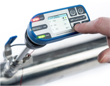
Figure 1. Typical Thermal Mass Flow Meter
If flow meters are not installed, one must do an “audit” to develop the flow profile. This requires current (or power) and pressure to be data-logged for all air compressors - for a period long enough to develop all typical production profiles, accurate calculations of flow to be made based on measured data and air compressor performance curves, and all compressor flow summed. Even if you are measuring worn-out air compressors, I recommend assigning full factory specified curve flows to the compressor, to be conservative. Data-log at 30-seconds or finer, depending on the load-unload intervals. This is how I have done most of my audits. One should not just scale current to flow by a factor. This will be very inaccurate.
In either method, flow metered or calculated flow, one must “dampen out” the flow values numerically (in the Excel model) if there are load-unload or start-stop compressors in the mix. They make the system appear more “peak” than it really is. If the load-unload interval is 2 minutes, I would run a 5-10 min running average on flow to smooth it out.
Then, adjust measured (flow meter) flow to air compressor intake flow, in volumetric units like “acfm” or m3/hr, not normalized units like “scfm” or “nm3/hr”. This profile becomes the basis for sizing air compressors, and compressor delivery is the rated at the intake of the package. Use the following formula:
- Intake flow = measured flow x 29.92 / Ambient pressure (mm Hg)
I also adjust my flow profile for pressure, since some systems are rather unregulated, and have large pressure variances. This takes more spreadsheet manipulation than you might want to do, but here is what I do, for every data sample:
- Adjusted flow at P2 = flow at P1 x [1 + unregulated ratio x (P2 – P1)/100]
For one large aerospace customer of mine, I got their thermal mass flow meter data, which they logged in their SCADA system, validated it, and summed it. In this case, I was recommending heat-of-compression dryers, so I didn’t add back dryer purge. See Figure 2. Note the high variance in flow, and the “two mode” behavior. Note also the high “noise” in the data. Even after dampening, the noise is significant.
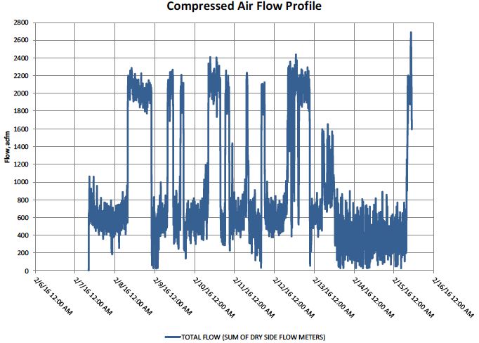
Figure 2. Flow Profile
In Summary
Develop an Excel model of the full range of flow that the entire compressed air system has to develop, for all typical production days, when the system is under a controlled pressure.
Determine Flow Ranges for “Trim” Air Compressors
This step requires “eyeballing” the above flow profile. That isn’t a skill I learned in engineering school, but in the real world of doing hundreds of compressed air analyses. In the aerospace project example, clearly there are two modes. High flow, which is a testing process that simulates airborne operation of auxiliary hydraulic units, and low flow, which is general pneumatics for HVAC plus maintenance. This is a “batch” process. Your plant might not vary this much. I am using this as an example, because at least half of my projects have large swings in air flow, and your plant might vary more than you think. Many operators say “my flow is constant”, and then I do the audit, and it has a large variance. It only takes one 1” valve to open to create a 1,000 scfm demand peak, and it might be muffled from the operators so they don’t know it’s happening.
First, throw out obvious outlier data. One typical data set to ignore is pumping up the system after it has been shut down. In this data set, it was always pressurized. Other outliers might be for a short enough period of time that you effectively ignore them for primary compressor sizing, and expect the back-up compressor to capture it. Like the peak on 2-15-16 at about 10AM in this data.
Second, look for ranges that are close to the same in max-min difference. This data shows two ranges that are about 800-1000 scfm max-min. See Figure 3.
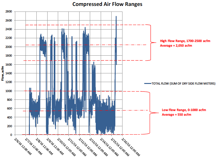
Figure 3. Flow Ranges
Size VFD & Base-load Air Compressors From Variance & Base-load Size
As described in the last article on sizing VFD compressors for single-compressor systems, you should stay in the 30% to 80% range most of the time. In this profile, the low end appears to go to zero often. Clearly, that is data noise. The system is too big to do that. So, if you wanted to size a VFD air compressor to magically work in those two ranges, you would want about a 1200-1300 acfm unit, with an 800-1000 acfm turn-down on speed control, or about 500-1300 acfm on speed control. However, you have to have a 1200-1300 acfm base-load compressor in the system to run at the high flow end, so your options are limited to the set of base-load compressors that make the most sense overall, and whether they are being replaced at the time the VFD is being installed.
I’ll stop here and give you a couple rules of thumb that can work well for multiple-compressor system design:
- Always have a sequencer, and one that can control the VFD compressor as “fixed trim”, not as one of the compressors that is staged in and out.
- Other articles have been written on this, but I like to have at least 3-5 gallons per acfm with oil free screw and 6-10 with lubricated.
- For fixed-speed compressors, equally-sized, sequenced compressors of the same type, with one spare at peak, is always the most robust design.
- Ideally, just one of them, and in its sweet spot, 30-80% speed, most of the time.
- To avoid “dead-band” control problems, the VFD compressor needs to be slightly larger than the base-load compressor, certainly not smaller.
I’ll run through three options on this flow profile, and you will see what works best. In the real world, it will depend on what base-load options you are constrained to.
Option 1. Two (2) Equally-sized Air Compressors (VFD and Base-load)
Air Compressor selections:
- (1) VFD: 1300 acfm, 500-1300 acfm speed range
- (1) Base-load (+ 1 standby): 1300 acfm/ea
This can work, if the flow doesn’t land in the mid range very often. As shown in Figure 4, this isn’t often the case in this system. However, if your demand floats randomly up and down, and would be in the middle 20% of the range a lot, I would not use this design. You would short-cycle between the VFD and base-load compressor frequently.
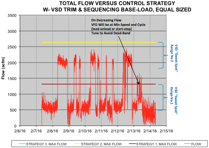
Figure 4
Here are some observations:
- Low Flow: VFD Cycles
- High Flow, VFD in Sweet Spot
- Look Out for Mid Zone, 1300-1800 acfm, “Dead Band
- OK for “2 Mode” Profile . BAD in Mid Range.
- Recommendation:
- Don’t use if flow is in mid range >10% of the time.
- Size storage and tune controls to dampen out transition from 1=>2 and 2=>1 compressors running.
Option 2. Larger VFD and (2) Equally-sized Base-load Air Compressors
Air Compressor Selections:
- (1) VFD: 1300 acfm, 500-1300 acfm speed range
- (2) Base-load (+ 1 standby): 750 acfm/ea
This is an attempt to follow the rules of thumb most rigidly, with available sized compressors. The challenge with this flow profile is the large jump. It outstrips one base-load and the VFD often, requiring the second base-load to start. See Figure 5. This would normally be a “best-practices” design if the flow varied more randomly. But this is the real world, so let’s see how it works. See Figure 5.
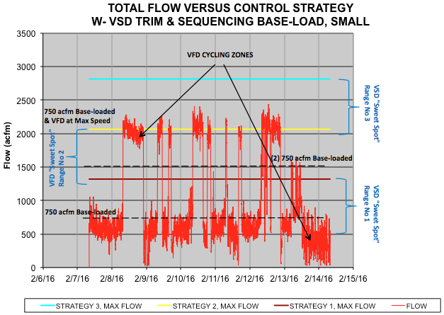
Figure 5
Here are some observations:
- Low Flow, VFD cycling in low range
- High Flow, After 2nd Base Starts, VFD swings back, cycling in low range
- Small base-load is GOOD in general, but watch the VFD low range.
- Recommendations:
- Size storage and tune controls to dampen out transition from 1=>3 and 3=>1 compressors running.
- Avoid 2=>3 and 3=>2 operation by sequencer timers. Give the VFD sufficient time to spin back and stabilize with two small base-load compressors running.
Option 3. Oversized Base-load Air Compressor
Air Compressor Selections:
- (1) VFD: 1300 acfm, 500-1300 acfm speed range
- (1) Base-load (+ 1 standby): 2000 acfm
This violates all the rules. I’m illustrating it to show why you shouldn’t do it. I have frequently had facility engineers clients who want to have a “large” base-load and a “small” VFD compressor. They are thinking about one load only, a flat demand at a flow rate they think they are at. They are not thinking about the flow ranges where this model falls apart, which will likely happen over the life of the system. In some cases, there is a newer large base-load compressor already in the system, and a new, smaller VFD trim compressor is added.
I call the middle range “no-man’s land”. Technically, it is a “dead band” control problem, where the control ranges of both the trim and base-load compressor are overlapping. Both will try to meet demand, and the system will be unstable. See Figure 6.
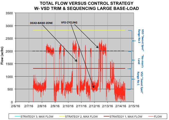
Figure 6
Here are some observations:
- Low Flow, VFD cycling
- Mid Flow, base-load & VFD cycle, unstable
- High Flow, VFD cycling
- Large Base-load BAD
- Recommendations:
- Don’t do it, if you can avoid it.
- If it’s unavoidable, use flow-based controls and upper range modulation with the base-load compressor so it runs the system alone in the mid range. This is a custom controller.
Conclusions
To match a VFD to a multiple air compressor system, do the following:
- Develop a solid flow profile
- Observe profile, and determine ranges for trim compressor to operate
- Always include a master controller and storage in the system, designed to control the trim compressor as “fixed trim”.
- In general, it is safest to size the VFD 1.5 X the base-load, and to have equally-sized, sequenced base-load compressors, with one spare.
For more information, contact Tim Dugan, tel: (503) 520-0700, email: [email protected], or visit www.comp-eng.com.
To read more Air Compressor Technology articles, please visit www.airbestpractices.com/technology/air-compressors.