There is always something new to learn about compressed air systems – particularly in regards to compressed air dryer installations. As I discussed in Part 1 of this series, you can make compressed air dryer installations more reliable by understanding the consequences of any modifications you make to the system. As a continuation of those ideas, Part II explores more ways to make a dryer installation more reliable. Discussions include: the difference between operating a desiccant dryer in a fixed cycle opposed to demand mode, what happens when you operate a heated desiccant dryer with the cooling air turned off, and how to deal with the unintended consequences of dedicating a desiccant dryer to a compressor.
Operating a Heated Desiccant Dryer: Fixed Cycle vs. Demand Mode
When desiccant air dryers switch towers, dewpoint levels often rise (or spike) for short periods of time. This is often called a “pressure dew point spike”. The smallest pressure dew point (PDP) spikes occur when the dryer is operating in the fixed mode. In addition, operating in the fixed mode allows multiple dryers to be synchronized so that the duration of the PDP spike isn’t extended by the spikes occurring one after the other. However, operating in fixed mode doesn’t save any energy. The higher PDP spikes that occur when the dryer is operating in demand mode can be reduced if the dryer is oversized and the dryer manufacturer provides a provision to extend the cooling air portion of the cycle.
One dryer manufacturer allows the cooling air to be turned on or off, and, when turned on, it can be extended from 90 minutes to 270 minutes. This dryer automatically turns off the cooling air when the PDP reaches -40â°F, so the dryer can switch towers. Therefore, the dryer must be oversized so that the cooling air portion of the cycle can extend for the full 270 minutes, allowing for the PDP spike to be reduced as much as possible. If all of the heated desiccant dryers in the plant were oversized so that the cooling cycle could extend for the full 270 minutes, the PDP spike would probably be small enough that there wouldn’t be any need to synchronize the dryers. Oversizing the dryer also reduces the pressure drop across it.
Operating with a Heated Desiccant Dryer’s Cooling Air Turned Off
Cooling air is required to reduce the PDP and temperature spikes that occur when a heated desiccant dryer switches towers. Activated alumina’s adsorption rate is reduced until its temperature is less than 120â°F, so a lower desiccant temperature in the offline tower produces a lower PDP and temperature spike at switchover. Because the temperature spike can travel a few hundred feet down the header, it’s important to ensure that nothing will be damaged by it when the cooling air is turned off. For example, one medical equipment manufacturer shut off their heated desiccant dryer’s cooling air, and their tubing products began melting.
In addition, the cooling air is important when the compressed air piping is exposed to low ambient temperatures. That said, not every plant contains items that can be damaged by temperature spikes. Nor does every plant have piping exposed to low ambient temperatures, so these plants can recapture compressor capacity by installing blower purge dryers and turning off the cooling air.
We have been shutting off the cooling air all year long on blower purge air dryers in chemical plants and refineries all along the Gulf Coast for years with great success. The cooling air can be turned off in northern states if the piping isn’t exposed to winter ambient temperatures. If the piping is exposed, the cooling air can be turned off during the summer when the compressor capacity is reduced by summer temperatures, but those plants must remember to turn the cooling air back on when colder ambient temperatures return. Why a blower purge dryer? In our experience, the blower purge dryer offers the best mix of energy efficiency and reliability. Other dryers may be more efficient, but, in our experience, they aren’t as reliable.
Effects of Compressor Cycle Time
Blindly dedicating dryers to compressors, as shown in Figure 1, can result in rapid cycling that can damage a compressor operating in load/unload mode, along with a desiccant dryer’s desiccant. For example, to prevent damage to their compressors, most manufacturers want a minimum 90-second cycle time for rotary screw compressors and a 2-minute cycle time for centrifugal compressors operating in load/unload mode. Also, modulating lubricated rotary screw compressors should have a minimum 90-second cycle time between sump blowdowns. Anything shorter than these cycle times is known as short cycling. While short cycling can damage compressors that are loading and unloading, it can also pump the oil out of variable speed drive (VSD) lubricated rotary screw compressors.
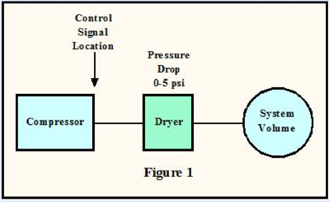
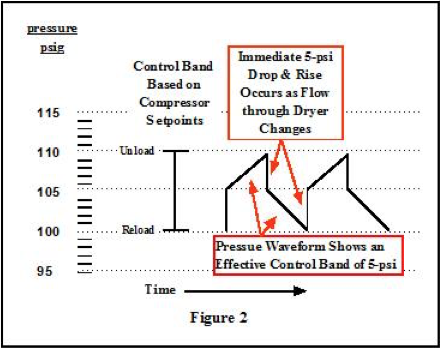
Typically, almost all compressed air system designs assume a pressure variation of 10 psi, so the compressor’s load/unload set points are often set 10 psi apart. However, that doesn’t take into consideration the change in the pressure drop across a dedicated dryer. For example, Figure 2 shows that if a dedicated dryer has a 5-psi drop across it when the compressor is fully loaded, it will have a 0-psi drop across it when the compressor unloads. Therefore, the actual pressure variation is only 5 psi. Reducing the pressure variation reduces the effectiveness of the system volume and cuts the compressor cycle time in half, which most likely will result in the compressor short cycling. Options to address the short cycling include:
- Increasing the spread between the compressor’s load/unload set points to compensate for the dryer’s differential (i.e. 15 psi apart).
- Install storage between the compressor and the dryer, which maintains the flow through the dryer. However, installing storage upstream of some desiccant dryers may not prevent a compressor from short cycling or the pressure upstream of the dryer from dropping to zero, because the offline tower is often pressurized with wet air from upstream of the dryer.
- Move the compressor control sensing point downstream of the dryer — done carefully to avoid exceeding the compressor pressure rating. However, in the case of lubricated compressors, this option too often results in an air/oil separator high differential pressure alarm, which — if high enough — can shut down the compressor. Therefore, in the case of lubricated rotary screw compressors, it’s best to install compressor automation if one intends to operate the compressor off the system pressure.
An additional issue exists if the dedicated dryer is a desiccant dryer with a bottom-to-top flow. In this case, when the compressor is controlled off the system pressure downstream of the dryer, the pressure between the compressor and its dedicated desiccant dryer’s outlet check valves can drop to zero when the compressor unloads. Consequently, the loading and unloading of the compressor may bounce the desiccant by causing the desiccant beads to grind against one another, slowly breaking them down. Piping multiple compressors into one dryer, with a backup or at least tie-ins for a rental dryer, has proved to be more reliable.
Many plants have multiple compressor stations with only one compressor and dryer in each, so it’s important to understand the issues associated with dedicating desiccant dryers to a single compressor. These plants could address this issue by installing storage between the compressor and desiccant dryer, but this means installing a receiver ahead of each dryer, which can be expensive. An alternative to installing storage is to install a bypass containing a check valve around the desiccant dryer that allows dry air to maintain the pressure upstream of the dryer, but doesn’t allow wet air to bypass the dryer. If the checked bypass is installed, the check valve should be replaced when the desiccant is changed. With centrifugal compressors, we try to load share across all the operating compressors, which either eliminates the need to load and unload a compressor, or minimizes it.
Managing Purge Air on “Heatless” Dryers
The purge airflow rate required by a “heatless” dryer can be calculated using the following formula:
QP = (Q * 1.15) / PR
Where:
QP = Purge Air Flow Rate
Q = Dryer Inlet Flow Rate
PR = (P+14.7)/14.7
P = Inlet Pressure
The 1.15 multiplier is a safety factor. The “true” pressure ratio between the drying and purging is the pressure within the online tower (i.e., after the pressure drop across the prefilter, inlet piping, and inlet valve, etc.) and the pressure within the offline tower. The pressure in the offline tower is equal to atmospheric pressure plus the pressure drop across the purge exhaust valve and muffler. The 1.15 safety factor accounts for a lower pressure in the online tower and a slightly higher pressure in the offline tower. In addition, the 1.15 service factor accounts for the fact that the regeneration time is shorter than the drying time due to depressurization and re-pressurization; therefore, the total purge (acf) used to regenerate the desiccant must exceed the total volume of air (acf) dried (averaged over time). The 1.15 safety doesn’t account for the pressure drop across the prefilter, inlet piping, and inlet valve, etc.
Let’s look at a couple of examples using a dryer rated at 1000 scfm at inlet conditions of 100 psig and 100â°F. For simplicity, assume that the pressure upstream of the prefilter is 103 psig, so the pressure in the online tower is 100 psig. Also assume the muffler(s) are clean, so the pressure in the offline tower is 0 psig. Under these conditions, the PR equals 7.803, so QP equals 147 scfm, which provides a flow of 1147 acfm in the offline tower. However, if the average inlet flow is only 800 scfm, then the purge flow rate can be reduced to 118 scfm. At an average inlet flow rate of 800 scfm, the 147-scfm purge rate will produce a PDP better than -40â°F, but if -40â°F is all that is required, why waste the air?
Dirty muffler(s) increase the pressure in the offline tower, which increases the required purge rate but doesn’t reduce the actual purge flow. The actual purge flow is usually set by establishing a high enough pressure drop across an orifice to reach “critical flow.” Above the critical pressure ratio, flow is a function of only the upstream pressure and temperature. Increased backpressure has no effect on the flow through the purge orifice until the flow becomes “subcritical,” which only occurs when the pressure ratio across the orifice becomes less than ~ 2:1 for air. However, the backpressure reduces the compression ratio, which reduces the flow in the offline tower and may require increasing the purge flow. Using the above example, if none of the other variables change, the 1.15 safety factor allows the backpressure to increase to 2.15 psig before the purge flow needs to be increased.
A lower pressure in the online tower reduces both the purge flow and the flow in the offline tower, so the purge rate should be increased to maintain the required PDP. Using the above example, if none of the other variables change, the 1.15 safety factor allows dryer to maintain the required PDP with the pressure in the online tower as low as 86 psig.
Finally, note that few dryers operate at design conditions 24/7, so even if the dryer is slightly “under purged” due to these effects, every time that air demand downstream falls below the design flow rate, the actual purge percentage increases so the dryer can play “catch up.”
Addressing Varying Flow Rates through Dryers
This meant that the plant had to increase the purge rate when the flow increased to 4500 scfm. When the flow through the dryers increased and the plant didn’t change the purge flow rate, moisture was found in the plant during the winter. In addition, with both dryers online, the normal flow through each dryer was only equal to 23 percent of each dryer’s rated capacity, which the dryer manufacturer says can create channeling through the desiccant. Channeling reduces or stops the flow across the capacitance probes, so the demand control didn’t function properly, which also resulted in moisture occurring in the plant during the winter.
In order to simplify the operation of the dryers and improve the system reliability, it was recommended that the plant set the purge rate of both dryers at 882 scfm. One dryer would then operate in demand control, while the other dryer operates in standby, which means that it operates in demand control with its inlet valve closed. This approach reduced the total purge flow rate from 1050 scfm to 882 scfm, and increased the flow through the dryer. Operators rotate the dryers on a monthly basis by opening the inlet isolation valve on the standby dryer and then closing the inlet isolation valve on the dryer that was online for the past month. Dew point and pressure alarms were installed to inform the operators when they needed to put the second dryer online.
Rental Compressors and Heat of Compression (HOC) Dryers
In an example from a petrochemical plant, one of three centrifugal compressors failed, so this particular olefins plant rented two 1600 cfm “oil-free” diesel-engine drive portable compressors. The HOC dryers had preheaters that required a minimum of 220â°F inlet temperature. The compressor discharge temperature was 250â°F, but the dryer inlet temperature was 238â°F — even though the pipe between the compressor and the dryer was insulated. The dryer desiccant was recently changed, and the dryer was drying the air to a PDP between -25â°F and -30â°F when the rental compressors were shut off.
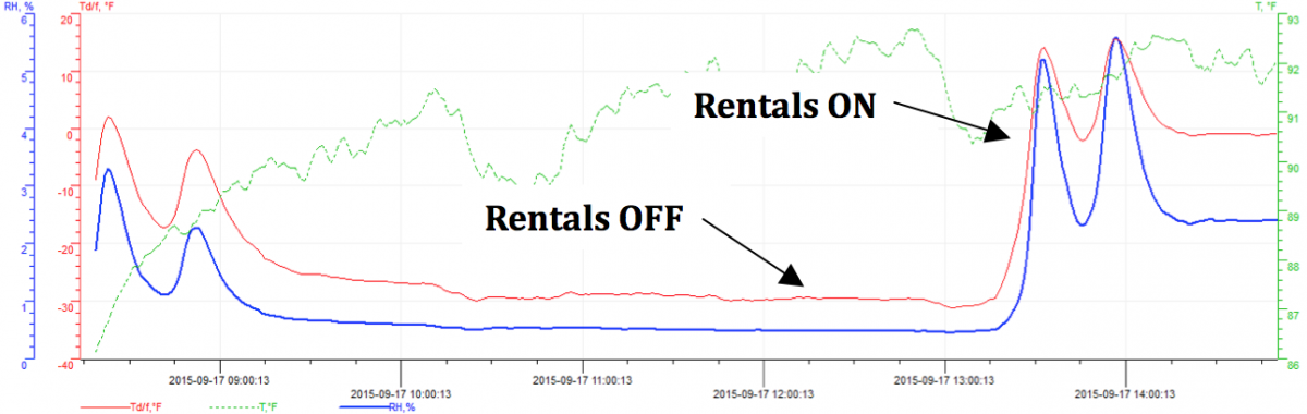
Figure 3: Differences in inlet temperature caused by rental compressors resulted in varying PDP and moisture in the plant.
Click here to enlarge
The rental compressors were connected to the header between the centrifugal compressors and the HOC dryers. When they operated, the dryer inlet temperature dropped to 180â°F, and the PDP of the air rose to +0â°F. The dryer inlet temperature was lower during the winter, so the PDP of the air was worse, causing moisture to occur in the system. When a compressed air audit determined the cause of the moisture, the rental compressors were connected to the wet air header downstream of a check valve so they couldn’t cool the air going to the HOC dryers.
Read Part 1 of this series.
For more information, contact Chris Beals, tel: 303-771-4839, email: [email protected].
To read more about Compressed Air Treatment, please visit www.airbestpractices.com/technology/air-treatment.