Compressed air is provided to power pneumatic valve actuators, drive air motors, convey raw material and products, activate analytical instrumentation, and for cooling services. To be effective, compressed air must be dried to remove moisture, and other contaminants, which contaminate and corrode critical components. Purity levels recommended for various services are given in Fig. 1.
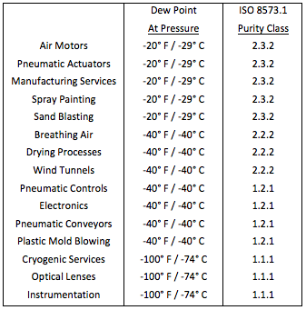
Fig. 1 – Recommended Compressed Air Dryness Levels
Adsorption devices are commonly installed in compressed air systems to remove moisture. Heatless compressed air dyers are the most common type furnished to meet the requirement for -40° F dew point “commercially dry” air, especially in systems of less than 1,000 standard cubic feet per minute (scfm). Heatless air dryers are pressure swing adsorbers designed to retain the heat of adsorption within the desiccant beds during the drying process.
The stored heat of adsorption is consumed during the regeneration process to remove moisture from the desiccant to provide continuous service. If the heat is lost prematurely, such as by excessive flow rates, the heatless dryer cannot regenerate and the system fails requiring priming at minimal flow for an extended period of time before continuing. The dryer is heater-less, but it relies on the retention of the heat of adsorption evolved during the drying process to provide continuous service.
The Inventor: Dr. Charles W. Skarstrom
|
|
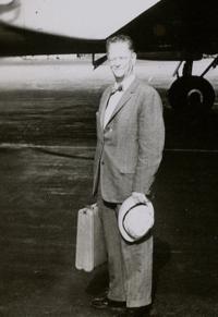 Dr. Charles W. Skarstrom, Inventor
The heatless dryer process was born out of necessity by Dr. Charles W. Skarstrom in 1956 at the Esso refinery in Bayway, New Jersey 1. Dr. Skarstrom, who had worked on the Manhattan Project during World War II, was developing an automatic gas analyzer for his laboratory when the plant’s desiccant air dryer failed. The dryer’s regeneration heater burned out. Acting on the theory of heater-less regeneration, Dr. Skarstrom solicited the assistance of Virgil Mannion and Robert C. Axt, adsorption system engineers, and together they shortened the dryer cycle time sufficiently to conserve the heat of adsorption and continue the drying process without an external heat source. Based on the successful operation, the process was patented 2. Dr. Skarstrom’s laboratory observations are preserved in his patent issued in 1960, and in the 1972 CRC Press publication 3. He discovered that to dry compressed air, the following principles must be applied for the process to continue.
- Principle #1: Short cycles and low throughput per cycle are required to conserve the heat of adsorption
- Principle #2: Regeneration at low pressure using some of the purified product for countercurrent purge
- Principle #3: Actual purge flow rate (acfm) must equal or exceed the throughput flow rate (acfm). The third principle can be restated in terms of standard cubic feet per minute (scfm):
Purge (scfm) > Feed (scfm) x (Regeneration Pressure, psig + 14.7) / (Inlet Pressure, psig + 14.7)
Microporous Desiccant Material
The desiccant in a heatless air dryer is a microporous mineral rather than a chemical reagent, and moisture is removed from the air by adsorption, a physical phenomenon, rather than by chemical reaction. Desiccants are rigid, nanoporous, sponge-like granules that provide a large active internal surface in angstrom size channels for attracting and retaining fluid molecules.
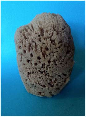
Fig. 3 – Natural Ocean Sponge adsorbents have Similar Microporous Structures
The physical attraction is the result of van der Waal forces and electrostatic interactions. These forces, explored by Johann Dietrich van der Waal (1838-1923) and Linus Carl Pauling (1901-1994) include polar attraction, London forces, and gravitational dispersion among other forces. The adsorption phenomenon was studied extensively by many researchers including Stephen Brunauer and Paul Emmett, who later developed the method for separating U-235 from U-238, and Edward Teller who led in the development of the hydrogen bomb. They devised the B.E.T. method of measuring the internal surface area of adsorbent granules 4. Recently research has shown that adsorbed water molecules are retained in a state differing from either a vapor or a liquid. Upon entry into the nanocavities, the atoms of the water molecules delocalize and adhere to the solid surfaces in a “quantum tunneling state”. The discovery was made by neutron scattering and ab initio simulations at the Department of Energy’s Oak Ridge National Laboratory (ORNL) in 2016 5.
Knowledge Developments in Heat of Adsorption and Adsorption Isotherms
Experimentation revealed that the heat released during the adsorption process is exothermic in accordance with J.W. Gibbs’ law. The atoms from the water molecules lose a degree of freedom during the adsorption process and the adsorption process is accompanied by a reduction in entropy (S) and Gibbs free energy (G):
âH = âG + T âS
This phenomenon is observed when liquid water is added to a flask of dry desiccant. The heat released is sufficient to produce steam shown rising from a beaker of molecular sieve desiccant.
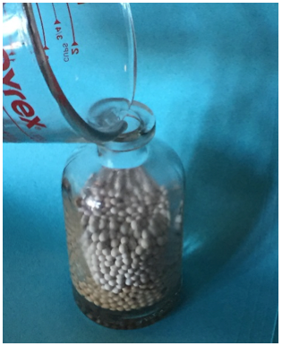
Fig. 4 – Energy is Liberated When Water is Adsorbed by a Desiccant
The released heat is absorbed into the compressed air stream by convection resulting in an elevation of the air temperature, âTa. The temperature rise is directly proportional to the heat of adsorption and to the change in specific humidity in the air, âW, divided by the specific heat of air, cp 6.
âTa = âH x âW / cp
The three common industrial desiccants are activated alumina commercialized by Pechiney in France in the 1950’s based on the Bayer process 7, synthetic silica gel developed by Walter Albert Patrick in 1918 (Grace Davison), and synthetic molecular sieve invented by R.M. Milton of Union Carbide (Linde) in 1959 8. The B.E.T. surface area of commercial activated alumina is about 350 square meters per gram, silica gel has a B.E.T. internal surface area of about 650 square meters per gram, and molecular sieves have an internal B.E.T. surface area of approximately 800 square meters per gram.
At partial pressures below saturation, the adsorption capacity for water vapor decreases, but not linearly. Stephen Brunauer, Lola S. Deming, W. Edwards Deming and Edward Teller studied the various isothermal adsorption capacity curves and published the five characteristic forms: 9
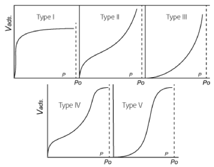
Fig. 2 - The Five Types of van der Waals Adsorption Isotherms
Dual Chambers and Fluidization
Desiccant is installed inside two chambers and the compressed air is directed into one chamber while the other is being regenerated. As recommended by Dr. Skarstrom, the flow through the regenerating chamber is countercurrent to the direction of flow through the chamber that is drying the compressed air 3. The wet air can be admitted into either the top or the bottom of the drying chamber. Depressurization of the chamber at the start of regeneration must be opposite to the direction of the drying flow. It is most practical to flow upward during drying so that the chamber will be depressurized downward to initiate regeneration. This causes the least disturbance in the desiccant bed and minimal adsorbent abrasion.
The compressed air is subject to energy losses and pressure reduction as it flows through a chamber filled with desiccant. This loss should never be so severe as to fluidize the desiccant granules or cause them to oscillate violently resulting in granular attrition. The energy losses in a fluid stream passing through a granule bed are expressed by Daniel Bernoulli’s law of hydrodynamic pressure, and more recently by Sabri Ergun 10. The vessel flow area must be sufficiently large to prevent the fluid velocity from reaching fluidization. To protect the desiccant granules, the upward flow rate is limited to approximately 70% of fluidization. The down flow fluidization limit is twice the up flow limit as the granules tend to nestle and retain stable positions as the flow presses downward. The catastrophic effects of excessive velocities through packed beds have been reported by Theodore von Kármán, Frederick A. Zenz, and Edward Ledoux.
As the flow passes through the bed of desiccant granules, hydraulic energy is reduced, and mass transfer and heat transfer waves are established. Water vapor is not adsorbed evenly throughout the bed, but rather starts at the inlet end and quickly forms a mass transfer wave that permeates gradually through the bed. As the water vapor is adsorbed, heat of adsorption is liberated forming a thermal front that advances through the bed at a much faster rate than the mass transfer front. The shape of the heat and mass transfer fronts and their rates of propagation have been defined mathematically by A. Anzelius11 in 1926, and by Albert Einstein12 in 1937. The solution was simplified for linear-equilibrium isotherms by an approximation offered by Adrian Klinkenberg13 in 1948 as given by the following equation:
![]()
For Type I Langmuir type adsorption isotherms such as for molecular sieve desiccants, the following solution offers improved accuracy 14.
![]()
The effluent water vapor concentration is determined from an analysis of the mass transfer front which is distorted by the short cycle time required to contain the heat of adsorption. The NEMA cycle time is normally 10 minutes, 5 minutes per desiccant chamber, to provide a -40°F pressure dew point. The time is shortened to lower the effluent dew point or to reduce the size of the dryer chambers. To provide a -100°F pressure dew point, the cycle time is typically shortened to 5 minutes, 2.5 minutes per desiccant chamber. Cycle times as short as 24 seconds have been used to reduce the size of a desiccant heatless dryer to a fraction of the standard size. The effluent water vapor concentration from a heatless dryer is determined from the following equation 6.
X = (ta3/t2) (co)2 (scfm x ρ0) / {M N Wd (Pr)2 [1 – (p3/p2)] } lbm water vapor per lbm air
A lower effluent concentration can be achieved by decreasing the cycle time, τa3, decreasing the inlet moisture content, co 2, increasing the excess purge flow ratio, Pr-2, or by increasing the desiccant mass, Wd-2 (Note: Wd is also included in “N”).
Heatless Compressed Air Dryer Observations
The heatless air dryer offers a design that is based on the most advanced scientific principles. Through the years, estimating methods have been developed to provide first approximations for designing, operating and maintaining heatless air dryers. Some of the observations are listed below:
- Inlet moisture content doubles approximately with every 20°F increase in inlet air temperature.
- Compressed air temperature increases 20°F to 25°F when adsorbing moisture at 100°F and 100 psig.
- The inlet pressure must be at least 40 psig, preferably 60 psig, to prevent excessive temperatures.
- Pressure loss through the dryer including prefilter and after filter should not exceed 5 psi.
- The regenerated vessel should be pressurized to at least 95% of line pressure before switch-over.
- Purge flow is increased by approximately 15% to account for heat losses from the chamber.
- Minimum purge is about 15% of the inlet flow rate based on operating at 100°F inlet and 100 psig.
- Rob Thomson’s rule: outlet dew point changes about 1°F with each 1°F change in inlet temperature.
- Depressurization air loss is approximately 10% of the purge loss, and the two losses are additive.
- Harry Cordes equation: Minimum contact time (10 Min. NEMA) = 0.75 + [0.0345 x (P, psig) ] seconds.
- Required mass of desiccant to retain the heat of adsorption is approximately 600 pounds of adsorbent per 1,000 scfm of air at 100°F and 100 psig operating on a 10 minute NEMA cycle.
- Desiccants: activated alumina (Type II isotherm) is standard, silica gel (Type IV) is used for lower dew points, and molecular sieve (Type I) for the lowest dew points and for inlet temperatures over 100°F.
- The chambers are filled with desiccant to the knuckle in the top head creating a distribution plenum.
- Upflow drying and downflow depressurization result in minimum desiccant abrasion and attrition.
- Moisture and temperature switch-over spikes, prevalent in heat regenerated dryers, are not present.
- Desiccant chamber safety valves, one per chamber, should be set approximately 10% over the maximum system operating pressure to prevent valve plug simmering or chattering.
- Thermal safety valves on the desiccant chambers are sized to relieve excess pressure resulting from the expansion of trapped air in a closed vessel caused by an external conflagration.
- Pneumatic control air tubing can be stainless steel, Teflon®, copper, and for indoor service, nylon.
With diligence and attention to design principles, the heatless dryer can be constructed to fulfill very stringent service specifications. Testing of the finished product at the design operating conditions before shipment is advisable to confirm expected performance. A properly designed, fabricated, and tested heatless desiccant compressed air dryer is assured to satisfy the application requirements.

The Heatless Compressed Air Dryer Assembly (Courtesy Aircel LLC)
|
Calculation Notations co = influent concentration of water vapor, lbm of water vapor per lbm of dry air cp = specific heat of air at constant pressure, btu/lbm-°F G = Gibbs Free Energy, btu/lbm H = enthalpy, btu/lbm M = adsorbent equivalent capacity, lbm water vapor/lbm of adsorbent N = number of mass transfer units, dimensionless p 2 = effluent system pressure, psia p 3 = purge exhaust pressure, psia P = influent system pressure, psig Pr = excess purge ratio, actual purge / minimum purge S = entropy, btu/lbm-°R t = parametric time constant, (1.8 minutes) ta = drying time, minutes T = absolute temperature, °R T = throughput parameter, dimensionless V = volume of water vapor adsorbed, cu.ft./lbm of adsorbent W = humidity ratio, mass of water vapor per mass of dry air Wd = mass of desiccant, lbm X = effluent concentration of water vapor, lbm water vapor per lbm air ρ0 = standard density of air, lbm per cubic foot (0.075 lbm/cu. ft.) |
By Donald White, Chief Engineer, Aircel, email: [email protected], tel: 865-268-1011, www.Airceldryers.com.
To read more Compressed Air Dryer Technology articles, please visit www.airbestpractices.com/technology/air-treatment.
Literature Cited
- White, D. H., “Regenerable Pressure-Swing Adsorption Systems,” Pall Corporation, Presentation at US Naval Research Laboratory, Wash., DC, April 23 (1986).
- Skarstrom, C. W., “Method and Apparatus for Fractionating Gaseous Mixtures by Adsorption,” US Patent 2,944,627 (1960).
- Skarstrom, C. W., “Heatless Fractionation of Gases Over Solid Adsorbents,” Recent Developments in Separation Science, Vol. II, p. 95, N. N. Li (Ed.), CRC Press, Cleveland, OH (1972).
- Brunauer, S., P. H. Emmett, and E. Teller, J. Amer. Chem. Soc., Vol. 60, p. 309, (1938).
- Kolesnikov, A.I., G.F. Reiter, N. Choudhury, T.R. Prisk, E. Mamontov, A. Podlesnyak, G. Ehlers, A.G. Seel, D.J. Wesolowski, and L.M. Anovitz, “Quantum Tunneling of Water in Beryl: A New State of the Water Molecule”, Physical Review Letters 116, 167802 (2016), Pub. April 22, (2016).
- White, D. H., and P. G. Barkley, “The Design of Pressure Swing Adsorption Systems,” Chemical Engineering Progress, pp. 25-33, (1989).
- Bayer, K. J., “Studium Ïber die Gewinnung reiner Tonerdi, Chem. Zeitung, 12, p. 1209. Ibid, 14, p. 736, (1890).
- Breck, D. W., “Zeolite Molecular Sieves,” John Wiley & Sons, (1974).
- Brunauer, S., L. S. Deming, W. E. Deming, and E. Teller, “On a Theory of the van der Waals Adsorption of Gases,” J. Amer. Chem. Soc., Vol. 62, pp. 1723-1732, (1940).
- Ergun, S., “Fluid Flow through Packed Columns,” Chem. Eng. Progress, 48 (2), p. 89, (1952).
- Anzelius, A., “Über Erwärmung vermittels durchstrÓ§mender Medien,” Zeitschrift fÏr Angewandte Mathematik und Mechanik, Band 6, Heft 4, pp. 291-294, (1926).
- Einstein, A., Ph.D. Dissertation, “EidgenÓ§ssische Technische Hochschule,” Zurich, (1937).
- Klinkenberg, A., Ind. Eng. Chem, 40, (10) 1992-94, (1948).
- White, D. H., “An Analysis of an Adsorption Wave,” AIChE Spring National Meeting, 86, (1988).