Key engineering considerations for balancing safety, reliability, and compressed air quality in hazardous facilities
In most industrial facilities, compressed air dryers are considered standard utility equipment. Engineers typically evaluate compressed air dryers based on dew point performance, flow rates, pressure drop and maintenance requirements. In hazardous locations, however, these criteria are only part of the equation. Equipment must also be designed to prevent ignition sources capable of triggering combustion.
Some industrial environments contain flammable gases or vapors capable of forming explosive mixtures with air. When these conditions are present during normal operation, equipment must be designed to operate without creating sparks, excessive heat or other potential ignition sources.
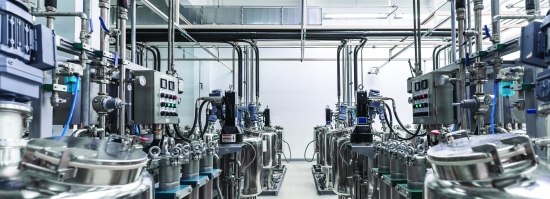
Production facilities with flammable gases or vapors, such as this pharmaceutical production facility, require equipment designed to operate without creating sparks or excessive heat.
Compressed air drying systems present a unique design challenge in these environments. While moisture removal is necessary to protect instruments and pneumatic tools, prevent corrosion and maintain reliable operation, the compressed air dryer itself cannot introduce hazards to the surrounding atmosphere.
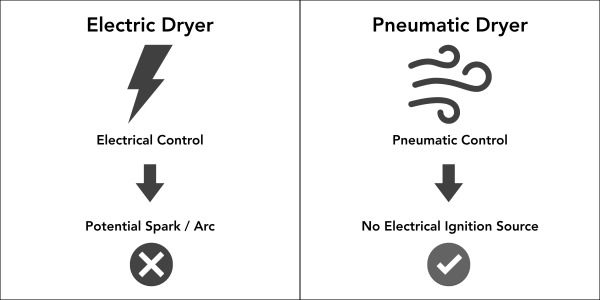
A comparison of ignition risk pathways in electrically controlled versus pneumatically controlled compressed air dryer systems.
This requirement fundamentally changes how engineers approach compressed air dryer design. Electrical control systems, mechanical contact surfaces, component materials and thermal behavior must all be evaluated through the lens of ignition risk. Rather than simply focusing on compressed air quality, engineers must design systems delivering reliable drying while ensuring the compressed air dryer can’t cause an explosion. This article focuses on twin-tower regenerative desiccant compressed air dryers, which are commonly used in industrial applications requiring low dew points and reliable moisture removal.
Understanding Hazardous Location Classifications
Hazardous locations are categorized based on the type of combustible material present and the likelihood the material will exist in an ignitable amount.
Class I hazardous locations involve flammable gases, vapors or liquids that may be present in the air in large enough quantities to produce explosive mixtures. Class II hazardous locations involve combustible dust rather than gases or vapors.
Within each class, environments are further divided based on how often the hazard is present. Division 1 indicates that ignitable concentrations exist during normal operating conditions. Division 2 indicates the hazardous material may appear only under abnormal conditions, such as leaks or equipment failures. These classifications guide the design and selection of equipment capable of operating safely in the environment. CID1 environments are often found in the oil and gas, chemical manufacturing, petrochemical, grain processing, healthcare, distillery and woodworking industries.
The consequences of equipment failure in these environments can be severe. Ignition of a combustible gas or vapor can result in catastrophic events involving fire, explosion, environmental contamination, equipment damage and significant risk to people. Because of these risks, equipment installed within hazardous locations must be carefully evaluated to eliminate or mitigate potential ignition sources.
Ignition Risks in Compressed Air Systems
Compressed air equipment may introduce several potential ignition sources if not designed for hazardous environments. Electrical components are among the most common concerns. Relays, circuit boards, wiring faults and switching contacts may produce sparks or heat if failures occur. Electrical arcs generated by switching devices can ignite combustible vapors or gases under certain conditions. Mechanical parts can also create hazards. Friction between moving components, contact between dissimilar materials and localized heating caused by mechanical wear can produce ignition sources.
Conventional desiccant compressed air dryers commonly use electronic controllers to manage regeneration cycles and valve switching. While effective in standard industrial environments, these electronic control systems introduce potential ignition risks if they are installed inside hazardous areas.
For this reason, engineers often attempt to isolate electrical components using explosion-proof enclosures. While these enclosures provide protection, they add complexity and rely on proper installation and maintenance to ensure their protective capability. An alternate approach is removing electrical ignition sources from the system entirely.
Eliminating Electrical Ignition Sources through Pneumatic Controls
One method for reducing ignition risk in twin-tower regenerative desiccant compressed air dryers is replacing electronic control systems with pneumatic control architectures. In this design approach, pneumatic timers and air valves are used to control the regeneration cycle. These components operate using compressed air pressure rather than electrical signals. By removing electronic controllers, the system eliminates potential spark-producing electrical components within the hazardous environment.
However, pneumatic operation alone does not guarantee elimination of ignition sources. Mechanical interfaces must be evaluated for friction-related heat generation or spark potential. During engineering review, potential contact points such as piston-to-base interactions and tower stud-to-spring interfaces should be evaluated to ensure they won’t generate hazardous conditions during operation.
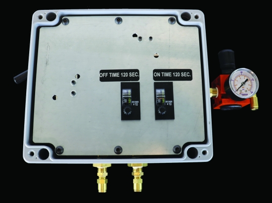
Pneumatic control components can be used to operate a compressed air dryer.
The goal of this approach is not simply replacing electronics with air-powered components. Rather, the goal is designing a system architecture that removes a major class of ignition risks while maintaining reliable compressed air dryer performance.
As one product development engineer involved in Class I Division 1 compressed air dryer design explained, “Engineers should always look at designing out the need for CID1 equipment. When not possible, engineers should always try to eliminate ignition sources through technology such as pneumatic controls.”
Why Moisture Removal Matters in Hazardous LocationsMoisture in compressed air systems can create reliability issues even in hazardous environments. Water vapor can condense within piping systems, causing corrosion, freezing and pneumatic instrumentation malfunction. Moisture can also degrade lubricants, affect valve operation and introduce contaminants to sensitive processes. In applications where compressed air is used for control instrumentation, excessive moisture may lead to inaccurate readings or delayed valve response. For these reasons, maintaining low-pressure dew point levels remains essential even in hazardous locations. The challenge for engineers is ensuring the equipment used to remove moisture does not introduce ignition risks to the surrounding environment.
ISO 8573 air quality classes are used to define compressed air contamination levels, including moisture content. Click to enlarge.
|

Pneumatic Controller Operation
The twin-tower regenerative desiccant compressed air dryer discussed in this article uses pneumatic controls in place of traditional electronic control systems. The compressed air dryer regeneration cycle is controlled by a pneumatic timing circuit alternating airflow between two desiccant towers. The controller operates within a defined pressure range. Minimum controller pressure is 80 psig (5.5 barg), while maximum controller pressure is 90 psig (6.2 barg), with 90 psig (6.2 barg) recommended for optimal operation. The pneumatic controller consumes approximately 1.5 cfm at 90 psig (6.2 barg).
The regeneration sequence is controlled using two alternating timing cycles. The ON cycle operates for 120 seconds, followed by an OFF cycle lasting 120 seconds. These cycles control a double-piloted valve directing compressed air between the two desiccant towers.
When the system is activated, compressed air flows through the valve, which directs airflow to one tower for drying. At the end of the ON cycle, the valve shifts position, redirecting airflow to the opposite tower while the first tower begins regeneration. Once the OFF cycle completes, the valve returns to its original position, and the sequence repeats. Because the timing and switching functions are controlled entirely by pneumatic components, the system operates without electronic switching devices inside the classified area.
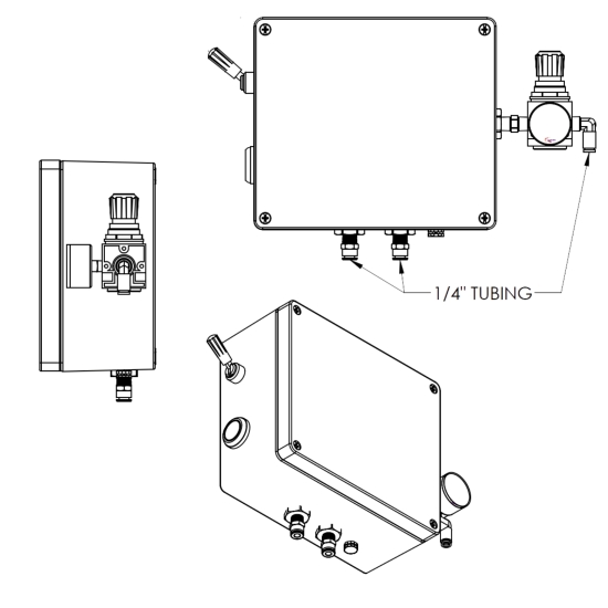
This pneumatic controller assembly illustrates the air-driven control system used to operate regeneration cycles in a twin-tower desiccant compressed air dryer configuration.
Thermal Considerations and Surface Temperature Limits
Temperature management is a critical factor when designing equipment for hazardous environments. Surface temperatures must remain below levels capable of igniting surrounding vapors or gases.
The compressed air dryer is designed to operate within an inlet temperature range of 33°F (1°C) to 150°F (66°C). Surface temperatures of compressed air dryer components are not expected to exceed this maximum inlet temperature.
While the system we’re discussing was not designed around a specific temperature classification rating, maintaining component temperatures within this range provides a safety margin in many industrial environments.
Engineers specifying compressed air dryers for hazardous locations must consider air compressor discharge temperatures, aftercooler performance and ambient operating conditions. If inlet temperatures exceed design limits, both drying performance and safety margins may be affected.
Compressed Air Dryer Performance Characteristics
In addition to safety considerations, compressed air dryers must meet performance requirements necessary to support reliable system operation. Pneumatic control architectures can be applied across a range of system sizes and configurations, from compact installations to higher capacity industrial systems.
The pneumatic-controlled twin-tower regenerative desiccant compressed air dryer discussed in this article operates within an inlet pressure range of 60 psig (4.1 barg) to 125 psig (8.6 barg). Under full load conditions, defined as a 100°F (38°C) inlet air temperature, 125 psig (8.6 barg) inlet air pressure and 70°F (21°C) ambient air temperature, with a rated dryer flow of 40 cfm, it achieves a pressure dew point between -10°F (-23°C) and 0°F (-18°C). When operating at approximately 75% of rated dryer flow, pressure dew point performance improves to between -25°F (-32°C) and -10°F (-23°C).
Higher inlet air temperatures of up to 150°F (66°C), and ambient air temperatures of 100°F (38°C) and above will impact the compressed air dryer’s performance. Under these higher ambient temperature conditions, expected pressure dew point performance is approximately 0°F (-18°C) under full rated dryer flow.
These performance levels demonstrate that pneumatic control architectures can achieve performance consistent with conventional electrically controlled desiccant compressed air dryers. In hazardous environments, maintaining stable dew point performance is critical, as moisture can lead to corrosion, freezing or malfunction of pneumatic equipment. Ensuring safety-driven design changes do not compromise drying performance is essential for reliable system operation.
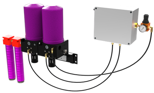
This compact regenerative compressed air dryer was designed for industrial compressed air applications.
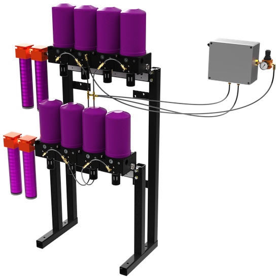
This larger capacity regenerative dryer configuration is used for higher flow industrial applications.
Pressure Drop Testing Results
Pressure drop across compressed air treatment equipment affects system pressure and stability. In hazardous environments, maintaining sufficient pressure is critical for the reliable operation of pneumatic controls and instrumentation. Excessive pressure loss can reduce system pressure to a point where control components may not function as intended.
Suburban Manufacturing Group conducted internal testing using a 40 cfm regenerative desiccant compressed air dryer operating at 100 psig inlet pressure. Measured pressure drop values were:
|
Flow Rate |
Pressure Drop |
|
10 cfm |
2.2 psig (0.2 barg) |
|
20 cfm |
3.3 psig (0.2 barg) |
|
30 cfm |
4.2 psig (0.3 barg) |
|
40 cfm |
5.9 psig (0.4 barg) |
These results demonstrate the increase in pressure loss as airflow approaches rated capacity. Engineers must account for this pressure drop when determining air compressor setpoints and evaluating downstream pressure requirements. Maintaining adequate and stable system pressure helps ensure the reliable operation of pneumatic components in hazardous environments.
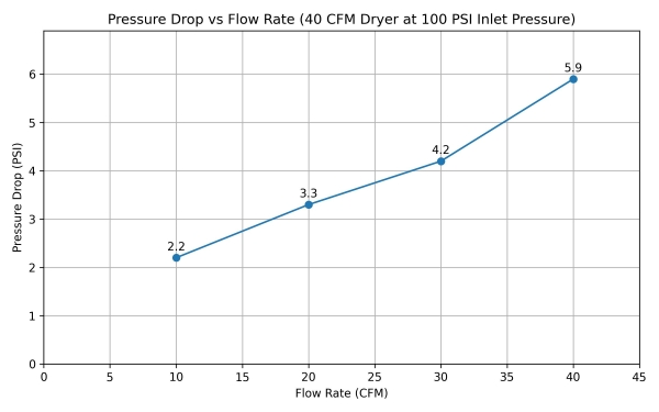
The measured pressure drop across a 40 cfm regenerative desiccant compressed air dryer at 100 psig inlet pressure.
Regeneration Dryer Compressed Air Consumption
Desiccant compressed air dryers require purge air to remove moisture from the saturated desiccant bed during regeneration. Total compressed air consumption includes both the purge air used for regeneration and the air required to operate the pneumatic controller. This demand must be considered when sizing air compressors and compressed air systems. In hazardous environments, undersized systems or unexpected air demand can lead to pressure instability, which may affect the performance of pneumatic controls and instrumentation.
For this table, measured air consumption values were obtained using a 40 cfm CID1 regenerative desiccant compressed air dryer operating at the listed pressures with 70°F (21°C) inlet air temperature and 70°F (21°C) ambient air temperature.
|
Inlet Pressure |
Air Consumption |
|
80 psig (5.5 barg) |
3.0 cfm |
|
100 psig (6.9 barg) |
3.6 cfm |
|
120 psig (8.3 barg) |
3.8 cfm |
Unlike some regenerative desiccant compressed air dryer designs, purge consumption in the pneumatic-controlled dryer evaluated in this article remains largely independent of airflow rate. Instead, purge demand varies slightly with operating pressure.
This characteristic simplifies system modeling because purge air can be treated as a relatively fixed load rather than a variable dependent on flow rate.
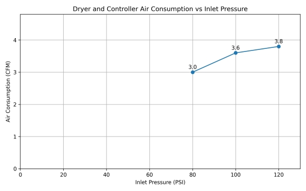
This chart shows compressed air dryer regeneration and controller air consumption across an operating pressure range.
Compressed Air Dryer Maintenance and Reliability Considerations
Equipment installed in hazardous environments must maintain reliable operation over long service intervals. Recommended maintenance intervals include filter service every six months and compressed air dryer tower maintenance every one to three years, depending on operating conditions.
The pneumatic-controlled regenerative desiccant compressed air dryer discussed in this article was first installed in 2016 at an oil refinery in Texas, requiring compressed air equipment suitable for a Class I, Division 1 environment. While detailed operational data from the installation is limited, no failures have been reported to date.
Although the installed base remains relatively limited, the use of pneumatic controls eliminates several failure modes associated with electronic control systems, including circuit board failures, electrical contact wear and wiring degradation. Reducing the number of electrical components inside the hazardous area can therefore improve long-term reliability while reducing potential ignition risks.
Engineering Considerations for Hazardous Location Compressed Air Dryer Design
Engineers designing compressed air systems for hazardous environments should first determine whether or not the equipment can be located outside the classified boundary (the defined area around a hazard where flammable gases or vapors may be present). Each hazardous environment is assigned a proximity radius, determining what types of equipment and technologies are permitted within that perimeter. If hazardous-rated equipment can be eliminated through system layout changes, overall risk can be reduced.
When equipment must operate within the hazardous space, engineers should prioritize eliminating ignition sources whenever possible. Control architecture, mechanical interfaces, thermal limits, airflow performance and maintenance requirements must all be considered when selecting compressed air treatment equipment.
Proper evaluation of these factors helps ensure compressed air dryers can deliver reliable moisture removal without introducing hazards into the operating environment.
About the Author

Jess Elley is Product Marketing Manager at Suburban Manufacturing Group, where she supports the Tsunami Compressed Air Solutions product line. She works with engineering and product teams to develop technical resources for compressed air system designers and industrial users.
About Suburban Manufacturing Group
Suburban Manufacturing Group is a U.S. manufacturer of engineered industrial solutions. Tsunami Compressed Air Solutions provides compressed air treatment equipment designed to improve reliability and air quality in industrial systems. For more information, visit https://www.gosuburban.com.
To read similar Compressed Air Treatment articles, visit https://www.airbestpractices.com/system-assessments/air-treatment-n2.
Visit our Webinar Archives to listen to expert presentations on Compressed Air Treatment at https://www.airbestpractices.com/webinars.