A newly constructed ethanol plant experienced control gap issues shortly after comissioning. This article discusses the cause of the issue and how the problem was solved.
Background
The ethanol plant is located in Canada and has an input of about 350,000 tons of grain resulting in an output of 130 million liters of ethanol. Within the plant power house is a compressed air system using three air cooled lubricated screw air compressors, two of which are VSD controlled, and a heated blower style desiccant dryer. A pressure/flow controller is used to keep the plant pressure at a constant 88 psi. The air compressors are controlled using a sophisticated central controller that operates the combination of air compressors for the best efficiency and provides a data interface so the compressed air equipment can be monitored centrally from the plant SCADA system.
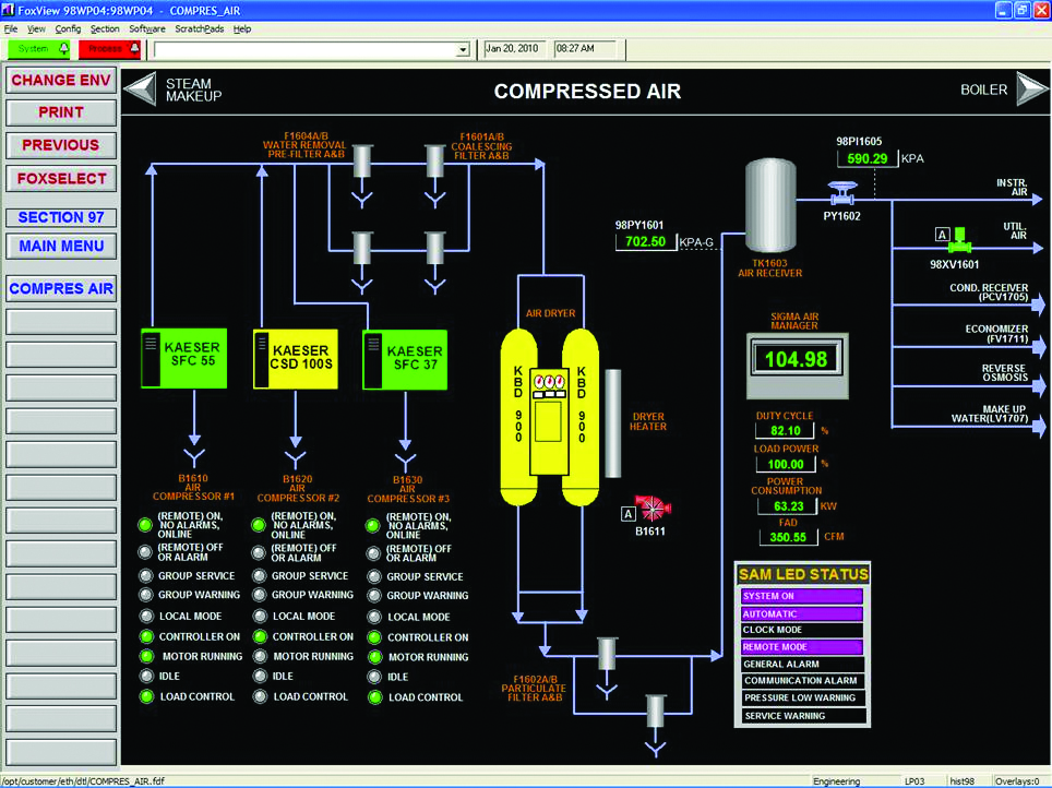
Figure 1: A central control system provides optimal control and data for monitoring. - Click here to enlarge.
Load Profile
The plant load profile is fairly flat, with most of the compressed air being consumed by general process operations the majority of the time with the occasional peak. The ethanol is produced in batches. During part of the fermentation process, a flow of compressed air is injected into the bottom of the fermentation vessel (Figure 2) to mix the liquid for better consistency. This flow occurs for 12 to 14 hours at a time. On top of this flow is a requirement for the air dryer cooling purge. After every air dryer regeneration cycle, a flow of compressed air is used to cool the heated desiccant so it is ready for the next drying cycle. These two additional loads cause a more or less consistent three-stepped flow characteristic.
Design Process
In the design stage, the engineering consultants, engaged to plan out and specify the compressed air system, counted on the step change of the compressed air flow to help them reduce the costs of the original design. The plan was to use VSD control to keep the system efficiency high, but there was an additional concern about the additional cost of the unit. Variable speed compressors have a cost premium compared to fixed speed units. To try to reduce costs to stay within budget, the engineering team sized the air compressors based on a particular estimated load profile where a fixed speed compressor would run during high flow agitation periods, with VSD trimming during vessel agitation. The other times, during the low load step, the VSD would run alone. This allowed the consultants to specify a smaller, less expensive 75 hp VSD to work with a 100 hp fixed speed unit.
Figure 2: Air is injected into the fermentation process for mixing. This causes a step change in flow.
During the design review stage, it was pointed out to the design team by external reviewers that use of a smaller VSD than the base unit results in a condition called “control gap”. When control gap problems occur, at flows between the capacity of the larger base compressor and the smaller VSD compressor, the two units will fight for control, causing undesirable and inefficient operation. The team was confident, however, that their calculations were accurate, and because the process flow was more or less constant and repeatable, a flow within the control gap would never occur.
The team made some good decisions on other aspects of the project:
- A central controller was specified to better control the air compressors
- A heated blower style dryer (Figure 3) was purchased with dew point control to reduce regeneration energy consumption
- Efficient filtering was specified to reduce pressure loss
- Airless drains were included to reduce compressed air waste
- A flow pressure/flow controller was installed to reduce plant pressure and limit artificial demand flow
- Air compressor room piping was sized to limit pressure loss, with consideration for additional future loads
- Large receiver capacity was installed to better stabilize pressure control and guard against large transient air demands
Figure 3: The blower style dryer saves 71 percent due to cool dry conditions and the dew point control.
Problems after Commissioning
As the reader could likely predict, the design calculations were off slightly. Murphy’s Law came into the picture. The compressed air system ran adequately for the first month or so of operation, as per Figure 4, where the 100 hp air compressor ran at full load and the VSD compressor at near minimum speed. This kept the base compressor at its most efficient point, but was a cause for concern for the long-term health of the VSD compressor. Operation at or near minimum speed is the least efficient point of the VSD flow vs. power characteristic (see Figure 6), and further to this, often at low flows inadequate heat is generated within the compressor to drive off moisture that condenses into the compressor lubricant. This can cause water damage of compressor internals and bearing failure. For this reason manufacturers recommend not to run VSD compressors at or below minimum speed for long periods of time.
As can be seen in Figure 4 the effects of the control gap started to become apparent. Near the last third of the graph some periods of time can be seen where the air compressors are fighting for control, with the VSD speeding up and slowing down, but at the same time the fixed speed base compressor inefficiently loading and unloading at a high frequency. There are some periods of low load where the VSD finally takes control and is the lone compressor running, this is the only period of good efficiency within the sample.
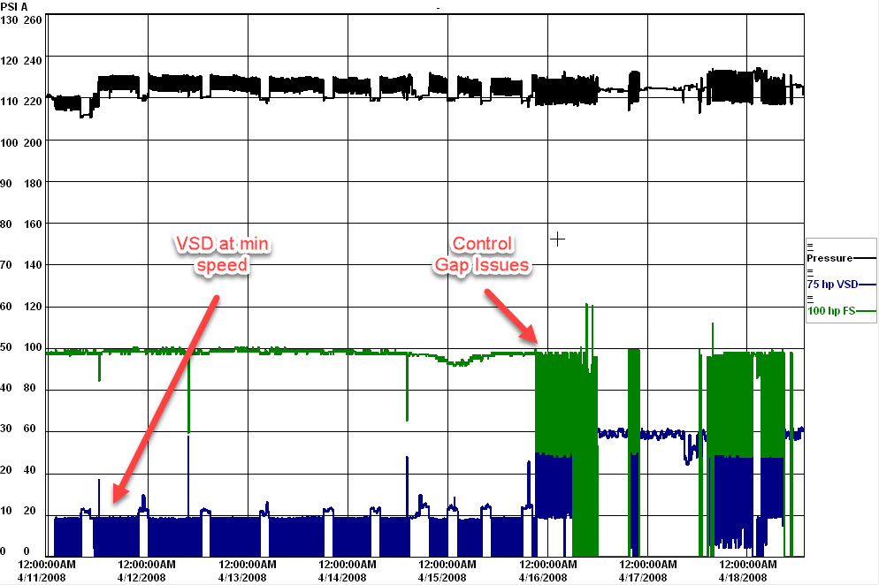
Figure 4: Compressed air profile during commissioning showed less than optimum compressor operation. - Click here to enlarge.
As commissioning progressed, the production staff found that additional unanticipated compressed air uses needed to be added to the production process. This increased the load to a point where the flow was almost always within the control gap, more than 90 percent of the time as shown in Figure 5.
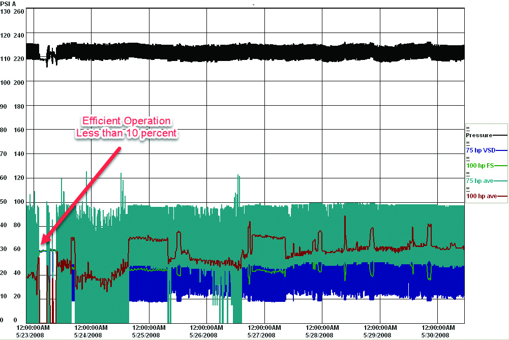
Figure 5: Load additions eventually pushed the system into the control gap most of the time. The compressors are fighting for control. - Click here to enlarge.
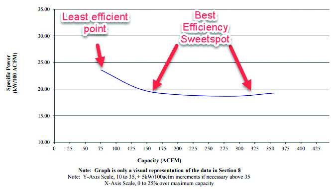
Figure 6: Best VSD efficiency is midrange. The central controller keeps the VSD compressors in this range. Source: Kaeser Compressors.
Solution
To solve the control gap issue, more variable capacity needed to be added so that this variable capacity was larger than the 100 hp base unit. A smaller fixed speed unit could have been added, but the site operators decided to install an additional 50 hp VSD compressor. This brought in the total variable capacity up to 125 hp, a size that ensures minimal VSD operation at below minimum speed, which is recommended by the compressor manufacturer. Fortunately, the central compressor controller has a built in algorithm that always seeks to keep the running VSD compressors between 30 and 80 percent of their capacity, which is the sweet spot of most VSD efficiency curves.
This change was not without problems, however. Sometimes, when a VSD compressor is placed on a central controller that takes its pressure sensing point downstream of a desiccant dryer, a delay is introduced to the control loop. This can make the VSD PID control loop unstable, causing the compressor to hunt up to maximum speed, then down to minimum speed with a sine wave characteristic. This type of operation can be seen on the first part of Figure 7. The manufacturer was consulted and instructions were given on how to tune the compressor control to make it less sensitive. This fixed the issue and the two VSD compressors started operating normally.
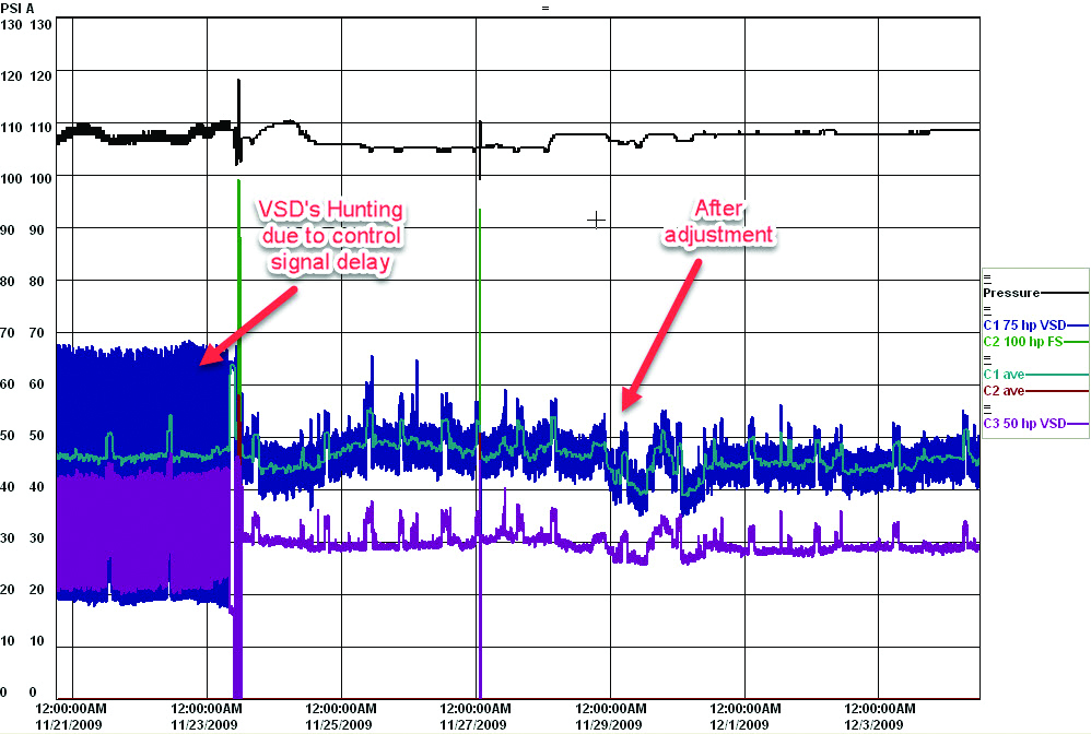
Figure 7: When the new compressor was installed problems with the control required tuning of the PID control parameters. - Click here to enlarge.
Conclusion
Good intentions to reduce costs in the purchase of new equipment can sometimes cause efficiency issues if the compressor sizing selection causes a control gap. The best bet to avoid control gap is to size the VSD capacity so that the variable part of the VSD capacity (capacity between minimum speed and full speed) is equal to or larger than the largest base compressor. If this is the case, it is possible to control the system efficiently from zero to full capacity with no inefficiency gaps in between.
The selection of a good control strategy or central system is important to the efficiency and pressure stability. A system that is smart enough to keep the installed compressors operating at their best efficiency point saves energy. The selection of other components like efficient filters, dryers, piping and drains makes the system even more efficient.
One important point about this system is that it was measured for verification after the installation took place. Many system operators assume that their system will operate efficiently, as designed and specified, and often no verification of the system is done. But, as we could see, some unexpected changes to the system caused poor system operation, something that would likely not have been noticed had measurements not been done.
And in case you are wondering, the plant is currently looking into more efficient low-pressure sources of compressed air for agitation.
For more information contact Ron Marshall, Marshall Compressed Air Consulting, tel: 204-806-2085, email: ronm@mts.net.
To read more Air Compressor Control articles, please visit www.airbestpractices.com/technology/compressor-controls.


