This is a two-part article looking at factors impacting decisions on whether to use air or water-cooled air compressors. It also provides heat recovery guidelines for both situations. Part 1 will provide a brief history on air compressor cooling, a review of cooling water sources and costs, and some cooling cost comparisons between air and water-cooled air compressors.
Brief Historical Background on Cooling
Before evaluating the air or water-cooling opportunities of air compressors, a little historical background is in order.
When the only primary industrial air compressor choices were reciprocating or centrifugal, the choice was, as it still is, what was best for the equipment and economical to run. The selection of the cooling media depended on several obvious factors – typical highest ambient temperature, continuous or intermittent load, total heat rejection, and most important, the type and design of the compressor.
From the 1930’s through the 1960’s the basic thought was heat transfers more efficiently through the cast iron cylinder and/or heads to water than air, because water is the denser fluid. Therefore, water-cooling is not only better but necessary in larger horsepower industrial grade air compressors, generally above about 100 horsepower. Units were designed with cooling water jackets to achieve this. Cooling water, or some other appropriate fluid, was required.
Air-cooled versions of 100 horsepower air compressors, and lower, generally had finned cylinders, heads, intercoolers and after-coolers, along with a cooling air fan. The fan may have been incorporated in the flywheel, driven off the main motor/compressor shaft, or separately motor driven. When it was all said and done, industrial air-cooled air compressors were not perceived to be continuous duty rated, meaning, they were intermittent duty rated.
Centrifugal Air Compressors Were (and Are) Water Jacket Cooled
Keeping in mind that cooling water was not very expensive in those days and often the cooling water was straight through – out of the river, through the air compressor and back to the river – well water was also available and of course city water.
As the cost of water and water treatment increased, various measures were taken to limit or control the use of cooling water such as series piping in lieu of parallel, recirculation ponds, etc.
During the late 1950’s and into the 1960’s, more demand developed for larger air-cooled air compressors, particularly for the portable engine driven market. These large, low rpm, water jacketed air compressors required large water-cooled, low rpm, engine drives that resulted in large, heavy units - a serious hindrance to portability.
Early on, small air-cooled, engine-driven air compressors were interfaced with the frame - also acting as an air receiver. The momentum changed in the 1960’s with the advent of the lubricant-cooled, rotary vanes and screws. The heat of compression generated in the compression chamber is now being controlled and absorbed by the cooling air flow. To have a successful application, the user only has to cool the oil. This can be done with an oil-to-air heat exchanger or an oil-to-water heat exchanger.
The heat of compression generated in this air compressor does not have to go through cylinder walls. To be removed, it is captured and controlled right inside the compression chamber as it is being generated. The result is a base air compressor design that is continuous duty rated (from a thermodynamic standpoint) with air or water-cooling.
The oil (or lubricant)-cooled rotary screw air compressors gained first acceptance as engine driven portables. As the products continued to develop through the 1970’s until today, they became more and more efficient and were accepted as an appropriate industrial compressed air supply. This also left the air-cooled or water-cooled selection a much more open question.
In existing industrial plants today, for 100 psig class compressed air supply, small air-cooled reciprocating air compressors and large reciprocating water-cooled compressors are used with the increasing number of lubricant-cooled rotary vane and screw, oil-free 2-stage rotary screw, and centrifugals. For new installations, you generally see air-cooled reciprocating (< 100-hp), rotary vane, rotary screw and centrifugal air compressors. The type of air compressor and size range will help dictate the type of primary cooling required.
A Review of Cooling Water Sources and Costs
When considering the direct operating costs of an air compressor, including energy, cooling water is often overlooked. Why?
- It may be difficult to isolate to the air compressor.
- It takes diligence to track and measure. Like anything, if you don’t measure it, you cannot manage it.
- Often the decision of whether to use air-cooled or water-cooled air compressors is dictated by the air compressor technology type, initial price, and general technical “sound bites.”
Generally today, air-cooling is often less expensive in capital costs, operating costs, maintenance costs, and floor space.
Regardless of what number is used for water cost (not including energy use) it will probably not be right for each particular location. This cost is very, very, site specific and should be the first factor identified when embarking on a water cost, energy control program.
Some thoughts on the various sources of cooling water:
- Municipal Cooling Water Over the last 40 years these costs have escalated rapidly reflecting the scarcity of water and particularly, the cost of water treatment. It is becoming the exception to the rule today to see a compressed air system cooling water supply coming from the municipal utility. If additional costs aren’t ignored such as sewer charges (for the water out) and various surcharges, the true cost is not always evident.
- Often, city water will still require water treatment for effective performance in industrial cooling. These costs must also be considered.
When companies react by no longer using municipal water, there are several other choices:
- Well Water: Has varying characteristics which are site specific but generally is not “Free.” After the well is drilled, in most parts of the world, the good news is that it is usually cool. The bad news is that it usually requires significant intake filtration and water treatment for industrial use. Electric energy is required to pump it out of the ground and through the equipment.
- Today, the cost of disposing of the heated cooling water has escalated as various agencies may limit the dumping of the heated water into streams, rivers and lakes due to potential thermal pollution.
- In many areas, well water supply is diminishing as the water tables may be lowering and as the well gets older, the total flow in gpm may well be falling off.
- River Water / Lake Water:
- River water and lake water all have the same limitations as well water with regard to intake filtration and water treatment. In many, if not most, areas today it is no longer “free” and there often is a charge for the discharge of heated water to the local body of water. There are also EPA regulations to be met and monitored with any water being discharged to this type of water supply.
All of these escalating costs, along with the man hours required to measure and manage the process, created great incentive for industrial plants to supply all their own plant water utility or supply.
The net result of these cost factors for cooling water has resulted today with most design engineers using a “default cost” of $3.00 (USD) per 1000 gallons of cooling water when the actual site situation is unknown. The accompanying water treatment cost is about specific situations and can be much higher depending on site conditions and maintenance diligence. An example is $1.20 per 1000 gallons based on 40 grains of hardness, alkalinity 10 and biocide treatment included.
Plants have had several options in light of escalating costs and regulations:
- Decrease the cooling water requirements. To avoid the escalating cooling water costs, compressed air systems have become prime targets for continuous duty, air-cooled, air compressors. The lubricant-cooled rotary screw and vane compressors offered good selections for greater than 100-hp unit market and over the years became the design of choice. The larger horsepower units being supplied, to a heretofore water cooled market, often developed issues in applications when installed such as lack of room ventilation, installation in too high of ambient temperature for proper compressor after-cooler and dryer performance, and maintenance personnel being unprepared for large air-cooled units.
Today, many of these problems are behind us due to effective training. During the last decade, however, many operations have laid off utilities maintenance personnel and either outsourced or ignored much of the routine maintenance. This has resulted in significant productivity improvements and showed no immediate adverse effects. After some time, however, negative effects have begun to show as trained local personnel were no longer on site or available. Budgets for overhauls were forgotten, cooling issues, particularly in air-cooled units, where lack of proper and timely action will have significant adverse effects became a problem. Often these problems were blamed on the cooling media – air. The truth is, water-cooled units, not maintained in a timely manner with regard to cooler condition (water treatment) will take longer to reveal and have generally larger problems more expensive to correct. What remains are operating units that are:
- Air-cooled air compressors, small and large, that perform well
- Larger air-cooled units with selection or application issues causing poor performance
- Water-cooled units that cannot be converted to direct air cooling
A Review of Cooling Water Sources and Costs
The stated rating for cooling water requirements is how many gallons of water per 1000 btu/hr is rejected into the cooling water flow.
Air compressors generate a high rejection load due to their very basic inefficiency – i.e. it takes 7 to 8 input horsepower to supply 1-hp of work in compressed air. This creates heat-of-compression, generated during the process reflecting this inefficiency. Energy input not converted to work shows up as heat. This heat has to be removed for the equipment to run and for the plant to be able to use the air. Particularly today where dry air is often critical, it must be reliably and effectively after-cooled and dried.
Table 1. Cooling water requirements for single-stage rotary screw air compressors
|
Typical Lubricant-cooled Rotary Vane or Screw Cooling |
Typical Values for Air Cooled Oil Coolers |
|||||
|
Air Compressor Capacity |
Water-cooled Oil-Cooler and |
Approx. gpm at 70°F |
Approx. gpm at 85°F |
Air Compressor Capacity |
Water-cooled Oil-Cooler and |
Approx. cfm |
|
250/62 |
150,900 |
6 |
10 |
250/62 |
156,300 |
8400 |
|
350/83 |
200,300 |
7 |
12 |
350/83 |
208,500 |
8400 |
|
500/120 |
276,700 |
11 |
18 |
500/120 |
287,700 |
12000 |
|
800/215 |
445,500 |
16 |
27 |
800/215 |
463,100 |
17500 |
|
1000/250 |
550,400 |
23 |
39 |
1000/250 |
572,400 |
28700 |
|
1200/300 |
668,200 |
33 |
56 |
1200/300 |
694,700 |
28700 |
|
1500/350 |
889,709 |
33 |
56 |
1500/350 |
920,000 |
36000 |
|
2500/500 |
1,543,000 |
49 |
79 |
2500/500 |
1,543,000 |
45000 |
* This data is general in nature and should not be used to select equipment. It is necessary to look at the specific engineering data for all equipment being used. ** System at 100 psig
Table 2. Two-stage compressor data – Reciprocating nominal reference
|
Bhp Class |
Discharge pressure psig |
Cap |
Inlet Air 60°F, Water 75°F |
Inlet Air 100°F, Water 95°F |
||
|
Air |
Gpm water required |
Air |
Gpm water required |
|||
|
150 |
125 |
772 |
335 |
16 |
370 |
16 |
|
200 |
125 |
1050 |
335 |
21 |
370 |
21 |
|
250 |
125 |
1300 |
335 |
26 |
370 |
26 |
|
300 |
125 |
1560 |
335 |
32 |
370 |
32 |
|
350 |
125 |
1840 |
335 |
37 |
370 |
37 |
|
400 |
125 |
2035 |
335 |
41 |
370 |
41 |
|
450 |
125 |
2340 |
335 |
52 |
370 |
52 |
Table 3. Comparing costs of water and air-cooled systems: Two-stage, lubricant-cooled, 100-hp rotary screw air compressors
| 547 acfm /111 bhp @ 100 psig -- Discharge 180-200°F |
Water |
Air |
| Gpm at 50°F Electric $.06 kWh at 8,600 hours/yr |
8 |
5.5 fan hp / |
| Gpm at 70°F |
11 |
N/A |
| Gpm at 80°F |
18 |
N/A |
| Total H2O pressure loss (psid) |
21 |
N/A |
| Vent fan Input Power |
1.1 kW |
N/A |
| Cooling Cost at 70°F H2O (H2O costs at $3.00 per 1000 gallons) |
$17,028/yr |
-- |
| Vent fan cost |
$568/yr |
N/A |
| Water & Electrical Energy Cost at $.06 kWh / 8600 hrs/yr |
$17,596/yr |
$2,580/yr |
| Total Heat Remaining |
303,000 btu/hr |
|
Table 4. Comparing Costs of water and air-cooled systems: Two-stage, oil-free, 200-hp rotary screw air compressors
| 856 acfm /193 bhp @ 100 psig -- Discharge 350 to 400°F |
Water |
Air |
| Gpm at 50°F Electric $.06 kWh at 8600 hours/yr |
22 |
11 fan hp / |
| Gpm at 70°F |
29 |
N/A |
| Gpm at 80°F |
48 |
N/A |
| Total H2O pressure loss (psid) |
-- |
N/A |
| Vent fan Input Horsepower |
1.75 kW / 3500 cfm |
-- |
| Cooling Cost at 70°F H2O (H2O costs at $3.00 per 1000 gallons) |
$44,892/yr |
-- |
| Vent fan cost |
$387/yr |
N/A |
| Water & Electrical Energy Cost at $.06 kWh / 8600 hrs/yr |
$45,279/yr |
$5,160/yr |
| Total Heat Remaining |
599,000 btu/hr |
|
Comments to the Preceding Tables
- All data is general in nature and should not be used to select equipment. It is necessary to look at the specific engineering data for all equipment being used.
- The required gpm is very dependent on several critical specifications:
- Intake cooling water temperature to the compressor or dryer
- The allowable air compressor discharge temperature – i.e. reciprocating, oil-free rotary screw and centrifugals easily handle 350°F to 400°F discharge. Lubricant-cooled units are limited by the cooling lubricant fluid but are usually a maximum of about 200°F.
- Do not use nominal horsepower class for evaluation rather the exact OEM rated flow (acfm) at full load operating pressure (psig) at what bhp (compressor shaft) and, most important, motor input hp or kW which includes motor and drive losses. Examine the differences in flow and horsepower between the standard factory packaged two-stage, lubricant-cooled rotary screw and the oil-free (air or water jacket cooled) rotary screw.
All this considered, looking at the differences in 100 hp and 200 hp cooling cost for municipal “once through” or city, compared to the operating cost of air-cooling at $.06 kWh / 8,600 hrs/yr, is at least 5 to 6 times greater using $3.00 per 1000 gallons for the water cost. It is obvious why plants are looking for air-cooled units whenever possible and seeking how to minimize water-cooling costs when air is not viable. These numbers do not include water treatment or pumping circulation costs.
Heat Recovery Guidelines for Air-Cooled Air Compressors
Air-cooling offers many opportunities, especially heat recovery. Lubricant-cooled rotary screw air compressors, factory packaged, particularly lend themselves to effective energy recovery in the form of heated air with up to 90+% of the motor horsepower in btu/hr available in the cooling air stream. If ducting heated air out for heat recovery, a few guidelines are in order:
- Be cautious of the allowable back-pressure in the ducting. Depending on the brand and model, the allowable back-pressure varies from 1/32 inch of H2O to 1/2 inch of H2O. Be sure the ducting has proper configuration and large enough cross sectional (Figure 1).
- If air is ducted in and perhaps filtered, design and maintenance are critical not to impair performance.
- Normally ducting air to the air compressor and out will not be enough ventilation to control temperature buildup in the room. The heat radiated to the room by the compressed air equipment and piping (30-35% potential) must also be considered, which will vary depending on the machinery design and other equipment in the room such as pumps, controls, electric boxes, etc.
Figure 1
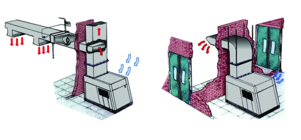
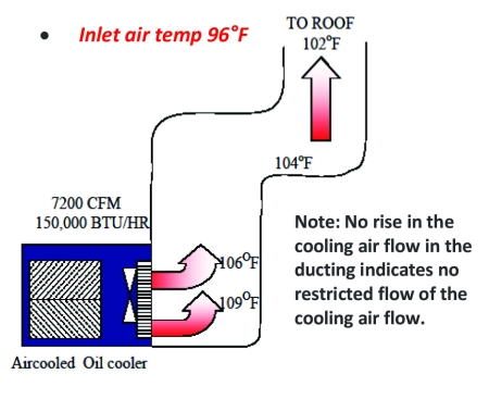
Figures 2 and 3 illustrate a well-sized duct system to remove the heated air from the room and on to another location. Note, when the duct wall temperature is checked, the cooling air moves further from the cooler and the temperature continuously drops. The air compressor is at full load and operating at normal temperature.
Figure 2. Cooling air ducting not working correctly
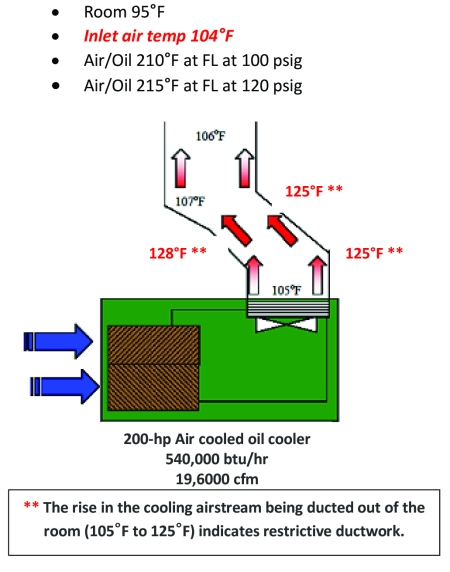
Figure 3. Cooling air ducting working correctly
Estimating Ventilation Required – Estimating Only, Not Designing
Heat Rejection for 100 hp Air Compressor Consuming 110 bhp
| Total heat rejection = | 110 bhp x 2,546 btu/hr |
| = | 280,060 btu/hr |
Air-cooled unit – rejection into ambient air: 280,060 btu/hr (100% of total)
Water-cooled unit – rejection into ambient air: 13% of total minimum / 30% of total maximum
Calculate Ventilation Air CFM (cubic feet per minute) from Heat Rejection
Cfm cooling air = (Sensible heat btu/hr)
(1.08)(T1 – T2) Temp Rise
Cfm = (110-hp)(2,546 btu/hr)
(1.08)(20°F)
Cfm = 280,060
21.60
Cfm = 12,966 cfm ventilation air to allow a 20ºF temperature rise in the room. Consider all heat sources in the room!
For more information on APenergy visit www.apenergy.com or call 740.862.4112
To read Part 2 of this article visit https://www.airbestpractices.com/technology/cooling-systems/evaluating-air-compressor-cooling-and-heat-recovery-part-2-centralized-systems.
To read similar Air Compressor Cooling Systems articles, visit https://www.airbestpractices.com/technology/cooling-systems.
Visit our Webinar Archives to listen to expert presentations on Air Compressor Technology at https://www.airbestpractices.com/webinars.