The pros and cons of using open tanks1 in central cooling systems was discussed in a previous article along with questions to determine if tanks were needed in any particular system. It is strongly recommended to review the Part 1 article if the reader is not familiar with the concepts presented on using or not using tanks including their capital and operating costs, efficiency impacts, and other system effects.
This Part 2 article will be of particular interest to industrial system operators unfamiliar with tankless (primarily closed) systems who may be considering either installing new systems without tanks or removing existing open tanks. The topics covered step through an understanding of tankless systems while also including tank system pointers and insights on converting systems with tanks into tankless systems.
If tanks are needed, the challenge is to use them effectively while minimizing the total associated costs. System operators should ensure they are not using them strictly out of custom or lack of understanding of closed systems.
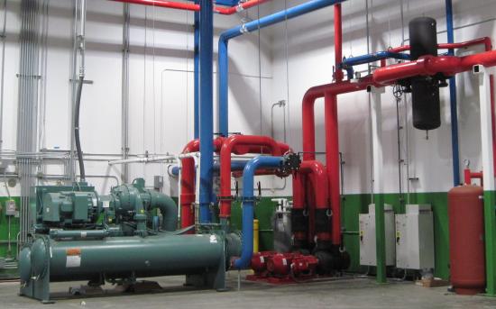
A 400 ton closed chilled water system.
Can Cooling Systems Even Work without Tanks?
For many system operators whose cooling systems have always included tanks, these concepts may seem unconventional or even dangerous and unsound. For them, it is worth noting that the vast majority of cooling water systems in the world do not have tanks.
Water is extraordinarily useful for cooling and is widely used in buildings ranging from commercial applications like hotels and offices to very large, multi-building facilities such as airports, hospitals, and expansive manufacturing complexes. Formal study of cooling systems in technical schools and universities focuses almost exclusively on closed systems as they easily make up over 90% of the systems in existence and all very large systems2.
In reality, central cooling systems using tanks are fairly narrowly limited to manufacturing and even then mostly to smaller systems and/or those in particular industries such as plastics converting or textile mills employing direct contact air washers for temperature and humidity control. In many cases, their use is as much a matter of habit and culture as it is technical requirements.
Cooling System Designs without Tanks
Tankless systems can be closed or open systems in central cooling plants. Closed systems are typically chilled water operating in a pressurized system with makeup water and an expansion vessel to accommodate volume changes in the system while maintaining adequately stable system pressure and good circulating performance.
In conventional HVAC applications, closed systems are the default design because they easily work with air handler coils and other comfort cooling devices that are not normally removed and reconnected as would periodically happen with plastic molds or other processing lines. They also readily accommodate significant elevation changes such as multistory buildings and sprawling systems such as college campuses without issues like draining down into a tank or loss of elevation head.
Typical HVAC systems rarely have meaningful water volume changes except from thermal expansion of the water due to the system being off for weekends or maintenance. While water specific volume only changes very slightly with the temperature ranges encountered in cooling systems, the resulting pressure changes could be catastrophic if not controlled. These requirements can be met with a quite small (relatively speaking) closed and pressurized expansion tank.
Outside of manufacturing, open tankless systems are almost always cooling tower systems where the towers are open to atmosphere at the water collection basin but otherwise have no tank. Manufacturing examples include open, direct contact cooling systems where the water is sprayed onto a product and collects in a return sump or else the product passes through a cooling bath through which the water flows constantly (e.g. via an overflow or other level control) to maintain the bath temperature as the product heat is absorbed.
Closed System Design Recap
Closed systems have important design features characterizing their use. The following are some of the hallmarks of closed systems relevant to their consideration versus open tank systems3 :
- Completely closed piping system with no open vessels or other atmospheric pressure-referenced elements in the normally sealed circulating system (see air vent item below)
- Operating pressure referenced to a controlled set point via the make-up water supply pressure reduction valve adjustment
- Appropriately-sized expansion tank using an air cushion to provide the pressure-referenced volume adjustment (either plus or minus) to avoid either system leaks from high pressure or loss of pumping ability from too low pressure. These often have rubber bladders to separate the air from the water and allow the tank to be installed at ground level.
- Piping design to provide flow through chillers4 and on to the cooling loads under intentional control for pressure, supply temperature, and other control set points; closed system designs may follow several standard designs such as primary – secondary systems or variable primary flow systems, or other situation-specific designs.
- Air and sediment separation equipment to remove air that enters the system (e.g. from newly installed molds or dissolved air in the make-up water) as well as undesirable matter like particulate debris in reconnected hoses, seal wear material, etc.
Most closed system components are generally identical to the components used in open systems including pumps, valves, piping, etc. The key differences are around the make-up, pressure control, and air removal, and these contrast with the typical open system issues such as management of greater air presence and potential draindown / overflow concerns.
How to Determine the Ideal Physical Location of a Cooling Tower
|
Closed vs. Open System Flow Design Features
A variety of flow designs can be implemented in closed systems such as single loop, secondary and tertiary subloops, and series pumping to meet differing cooling requirements such as low delta T applications, special pressures, etc. with the configurations only limited by hydraulic considerations and practical necessities.
Open systems are generally limited to a single open point per loop such that a recirc and process loop system can have separate open tank hot and cold wells, but not two open tanks in the same loop. This can in fact be done but it requires very careful execution to avoid draining the system through the lower tank (if they’re not at equal heights) or overflowing one by overpumping one direction or another.
The most common series open design concept is gravity flow from a cooling tower lower collection basin draining into an indoor tank for freeze protection; unfortunately the periodic freeze protection costs the loss of the pump suction elevation head from the tower height the entire time the system is operating. Air washer systems in textile facilities are the most common series tank systems with multiple open air washer unit basins, sometimes at different elevations, returning back to a chilled water sump in the mechanical room.
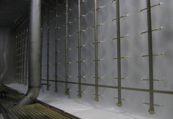
Open direct contact cooling in an industrial air washer.
Closed System Design Tips / Application Notes
Closed systems require particular design and operation practices to ensure reliable operation. These include needed components as well as the methods of installation and operation listed below:
- Ensure the make-up water supply pressure reduction valve is readily accessible and checked periodically. Systems that should be at 15 – 20 psi at the pump suctions are often at 35 to 40 psi or above due to poorly calibrated or malfunctioning pressure reduction valves, although in some cases the suction pressure may need to be higher for systems with elevated cooling loads like blown film penthouses, etc.
- The make-up water connection is typically made at or near the expansion tank close to the main pump suction. The expansion tank should never be installed on the discharge side of the loop pumps.
- The expansion tank in industrial systems should be sized to meet the particular system requirements for water delivery (e.g. the volume needed to nearly instantly fill a mold being installed) in addition to receiving water from thermal expansion or other sources.
- If separate heat-rejection recirculation and heat-absorbing process cooling loops can’t practically be converted to a single flow loop, the next best improvement is carefully managing the flows between the recirc and process loops. This could be either through flow rate matching using flow meters or other control method to calibrate the relationship between the two loops.
- Flows can be deliberately mismatched when needed for specific purposes such as low delta T molds and chillers needing higher delta Ts.
- If many of the cooling loads use process temperature control units with integral pumps (e.g. Mokon, Thermolator, etc.), the main loop flow conditions will be greatly improved by using TCUs with modulating control valves instead of the on / off solenoid valves.
- Air removal equipment should include an in-line, full flow, vented, separator (usually a combined air and sediment device) at or near the system low pressure point (hydraulically near the expansion tank) as well as air vents in system high points.
- The separator should be installed at a height near the system high point in the mechanical room where the total system flow comes through the process return piping.
- Any high points that exist should be equipped with air vents as they will be at lower pressure and any entrained and dissolved air will be likely to emerge from the water in these locations.
- In-line sediment removal equipment (whether including an air removal capability or not) should have a blowdown pipe connected between the separator bottom discharge and a drain point.
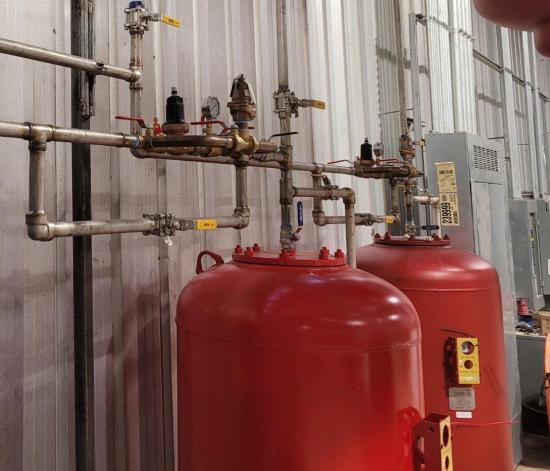
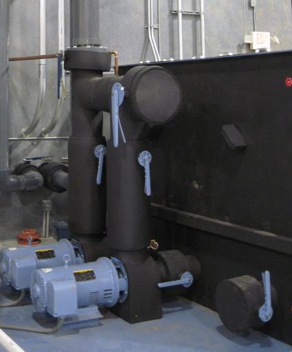
Make-up water valves and expansion tanks for two separate closed systems.
Air separator in a closed cooling system.
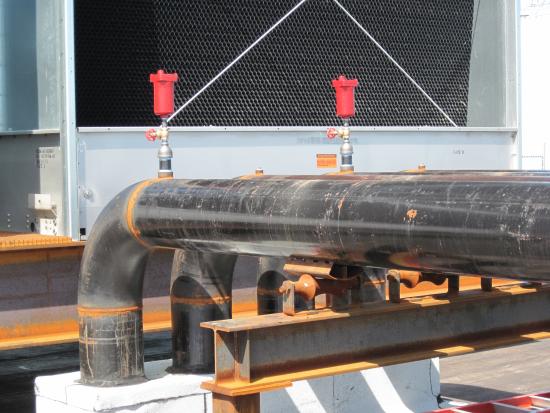
Air vents on a closed cooling system piping, note at end of run in flow direction.
Open Tankless System Design Tips / Application Notes
Open tankless systems have many closed system design features with a few distinct differences. In particular, the pressure regulation and system volume management are performed by the open location(s) with a common effective water level for multiple open locations. Other considerations for these systems include:
- Open systems need rigorous air management – air vents, air trapping design, etc. – to ensure air removal. Air blended into systems 24/7 can be mitigated by high flows but with higher energy use. Aggressive air capture designs such as full size tees with vertical branches can offset this at lower velocities.
- True counterflow cooling towers have higher air loads from the free fall of water into to the collection basin and the resulting splashing and entrained bubbles. These should be used in very concise systems such as chillers right inside the plant wall or heat exchanger-isolated systems.
- Extra care is needed on pump NPSHA / NPSHR for direct contact cooling return pumps where very low suction heads and potentially high suction piping losses can be expected.
- Direct contact cooling return pumping is not as difficult as it may sound as these are often very succinct systems. These are typically small vs. the total system loads and can be simplified by isolating each loop behind a heat exchanger and using VFDs for pump control.
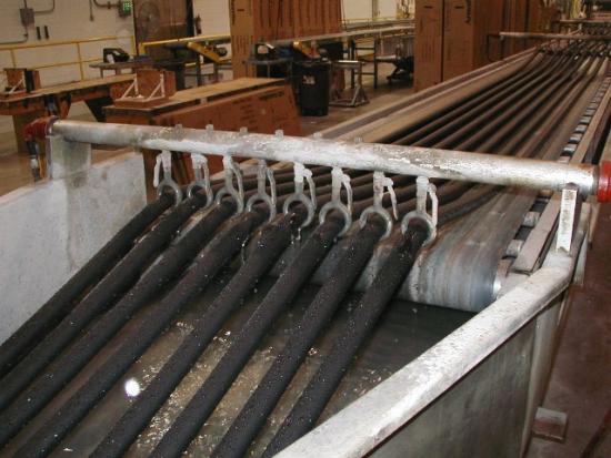
Foam insulation emerging from direct cooling water bath.
Cooling Systems Using Tanks
Systems with tanks will operate more effectively by following these design and integration measures:
- Use tanks only as hot wells with no recirculation between hot and cold wells (i.e., single tank only systems) to reduce the extra pumping and wasted diffusion head losses.
- Size the tank volume for projected lifetime needs as it is typically difficult to expand tanks once installed.
- For normal flow-based sizing, use larger tanks vs. expected flow. Instead of 2 – 3 gal. per GPM, design for 5 – 6 gal. per GPM or more at the expected ultimate flow rates, not just the initial design conditions.
- For thermal-based sizing, larger tanks will also provide more benefits; sizing will require careful calculation of the thermal cycle loads and is beyond the scope of this article.
- There are no benefits to having smaller tank. Long term costs will far exceed the lower initial expense.
- Select tallest possible tank for better operating water level and good pump suction supply pressure.
- Closely verify the required NPSHR for pumps used vs. NPSHA in tank – more cushion is always better.
- Design the piping to prevent draindown of the return by ensuring absolute below surface return and highly effective air removal. Only use inverted U returns or valve control if unable to resolve otherwise.
- The best returns are made to low level, tank-side, factory installed connections instead of through pipes draining into the tank from above.
- Use water diffusion on the return such as redirection elbows / tees, perforated pipe, etc. to blend return water in the tank without excessive surface turbulence to reduce air entry.
- Leave access room and preinstalled connection valves for future growth.
- Plan pumps for expansion through smart pump sizing (e.g., potential to upsize in place using same volute), additional pump suction outlets, etc. to avoid future crowding.
- Keep the tank as tightly closed as possible to eliminate dirt entry.
- Design for eventual removal of the tank if possible – isolation valves, pumps with curves to support closed operation, etc.
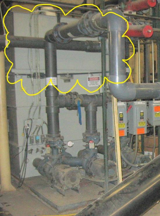
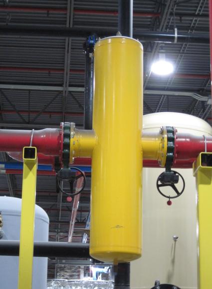
Tank with height extended to increase pump suction head (yellow cloud).
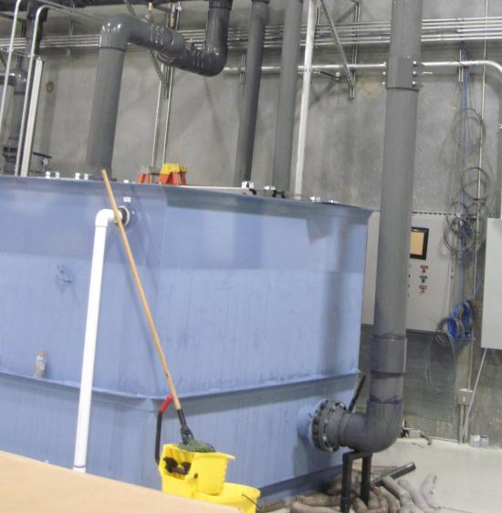
Return pipe attached at factory-installed low point connection.
Future pump connection on tank at installation.
Converting Systems Using Tanks to Tankless Systems
Where it has been decided to remove existing tanks, the following conversion tips will improve the performance of the revised system:
- Most tank pump systems are built with mechanical connections that can be used for revising the piping without field cutting.
- The tank and supporting frame can often be cut away from the pumps for their reuse with minimal revision.
- In some cases, it is better to remove the pumps frame also to recover additional height for the pump discharge components (see next point).
- OEM pump systems often install the check valve directly on the pump outlet as the small diameter enables the use of a smaller check valve resulting in higher check valve pressure loss. The extremely turbulent, high velocity pump discharge flow results in many check valve failures (spring-loaded, dual plate wafer designs frequently fail in this use). Relocating the pumps to short pads provides more vertical room for better designed discharge and check valve installation in the revised system.
- A new pump suction manifold to replace the tank connections should be oversized for low velocity / low distribution pressure loss so that there are near uniform suction pressures and suction entry flow conditions across the pumps. Use a large diameter pipe, typically 2X the suction diameter or larger; and the pipe should be larger for more inlet connections and / or pumps.
- Closed loop pump systems must be designed for thermal balancing of the flows, not just hydraulic balancing. If there are multiple returns and / or split piping from the pump discharges, then there must be a common flow pipe section to fully blend the separate returns. Ignoring this can cause poor chiller loading and water temperature control problems in different branches.
- The thermal balancing concern is especially important when there are different branches intentionally run with higher and lower delta Ts, particularly where tanks were deemed not needed for thermal blending. The oversized suction manifold is not intended to provide meaningful thermal smoothing to the system.
- Include a clean out port on the pump suction manifold. A 3” port with full size valve at the bottom center will allow for periodic cleaning.
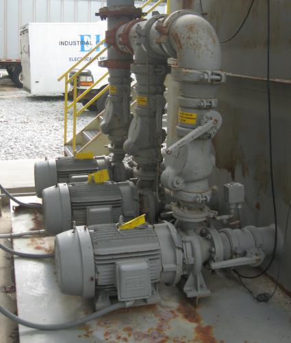
Pumps with factory installed mechanical connections.
Conclusion
Open tanks can serve an important role in central cooling systems but are not required except in select cases. Many more systems can operate better without tanks and their associated costs. Tankless systems, including both closed and open designs, set the stage for higher energy efficiency and other operating benefits if properly implemented and managed.
This article has reviewed key principles of tankless systems and has also provided recommendations for implementing both closed and open tankless systems. Additional suggestions are presented for systems with tanks and for converting tank systems to tankless if not required in a particular system.
Hopefully this and the previous article on tank applications help system operators better understand cooling system design options, leading to improved energy efficiency and system performance with lower capital and maintenance costs. ISG is grateful to Chiller & Cooling Best Practices Magazine for the opportunity to present these concepts and looks forward to questions on the material presented.
1As before, “tank” here refers to open reservoir tanks at atmospheric pressure as distinguished from closed tanks for pressure control, hydronic applications like thermal storage, or integral processing applications.
2Since most systems are for HVAC, the few open loops studied in these courses are the cooling tower systems supporting the closed system operation and not open loop process cooling applications.
3This list is by no means a complete design primer for closed systems. Seek additional information beyond the short list of points provided here if engineering a new closed system.
4Other cooling sources such as cooling towers or loop isolation heat exchangers can be similarly piped but chillers are the predominant cooling resource in closed systems.
For questions or more information about Integrated Services Group visit https://www.isg-energy.com, email: [email protected], tel: 770.823.8235.
For similar articles on Cooling Technology please visit https://coolingbestpractices.com/technology/cooling-towers.
Visit our Webinar Archives to listen to expert presentations on Cooling Technology at
https://coolingbestpractices.com/magazine/webinars.