An important manufacturing plant based in the U.S. southwest was spending an estimated \$2.5 million annually on energy to operate the compressed air system at its plant. The plant was also experiencing production downtime and quality issues due to the presence of moisture in the compressed air.
Our team conducted a compressed air audit of both their high-pressure system (100 psig) and their low-pressure system (55 psig). The result was a series of energy conservation projects able to reduce these energy costs by approximately \$415,655/year or 20% of current use. In addition, these projects will enhance productivity and quality by stabilizing pressure and eliminating moisture in the compressed air.
All of the calculations in this survey are based upon the site conditions of 8,760 working hours per year and a blended electric rate of \$0.088 per kWh.
The major savings identified in this system assessment were on the supply-side of the system and had to do with upgrading to a new air compressor and new cycling dryers. Another significant project involved storage and the use of a flow controller.
In this article, we will provide detail on the characteristics of the baseline system and then share the energy-saving work identified in two projects. These two projects represent work which can be performed by the maintenance teams in every plant. These are also project opportunities we find in almost every plant we visit. The two projects are to (1) repair/replace condensate drains wasting compressed air and (2) to perform a compressed air leak survey.
Characteristics of the Existing Compressed Air System
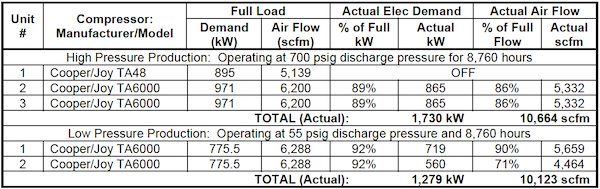
The compressed air system is supplied by four TA6000, 3-stage centrifugals, two 250-hp class high-pressure compressors, and two 1,000-hp low-pressure units. An additional TA48, 3-stage centrifugal 1,250-hp class is the high pressure swing unit. The air compressors are apparently very well cared for and maintained and experience timely and professional maintenance. At the time of the survey, they were 6 to 7 years of age and running very well.
Compressed air is dried by three non-cycling, shell-in-tube heat exchanger, refrigerated dryers. One dryer is for high pressure and one for low pressure. The third dryer is for either high or low pressure and is used as a swing dryer. During our site visit, the high-pressure refrigerated dryer had a 10 psid pressure loss and was not drying the air as it should. This was during a moderate temperature day with 50°F (10°C) ambient temperatures and 34% relative humidity. Significant amounts of condensate are in the high-pressure header and showing up in the packaging area. This will increase during the hot and humid weather this southwest plant sees every year.
The plant intends to expand production in the near future. This will increase the high-pressure air demand by 139 cfm and the low-pressure demand by 300 cfm.
Potential safety compliance issues exist. There are five 80-gallon vertical ASME code air receivers in palletizing that do not have safety valves installed. The plant should immediately install appropriate safety valves that are compliant to local codes. There are also a few 20 to 30-gallon air tanks that should be reviewed with regard to the same situation.
Calculating the Baseline Compressed Air Flow Demand
Two newly calibrated, heated wire, thermal mass, flow meters were installed at the plant. One was installed in the 10” header of the high pressure air line and one in the 12” header of the low pressure air line going from the air compressor room to the production areas. These flow meters revealed the following flow profile.
Table 1. Compressed Air Demand at the Plant
|
|
Flow (scfm) |
Pressure in Pipe |
|
Low Pressure Air System |
10,123 to 11,406 scfm |
55 psig |
|
High Pressure Air System |
10,662 to 11,476 scfm |
100 psig |
|
Expected Future Demand |
|
|
|
Low Pressure Air System |
300 scfm additional |
55 psig |
|
High Pressure Air System |
139 scfm additional |
100 psig |
The above numbers reflect operating the compressed air system during normal full production with the high to low bypass valve open.
To establish a proper baseline we analyzed two weeks of running power data supplied by the plant. Using Compressed Air Challenge curves, we show an average low pressure flow of 10,123 and is sustained with peaks of 11,400. The high pressure data showed average flow is 10,667 scfm with a sustained peak of 11,470 scfm.
Table 2. Existing Compressed Air System Characteristics
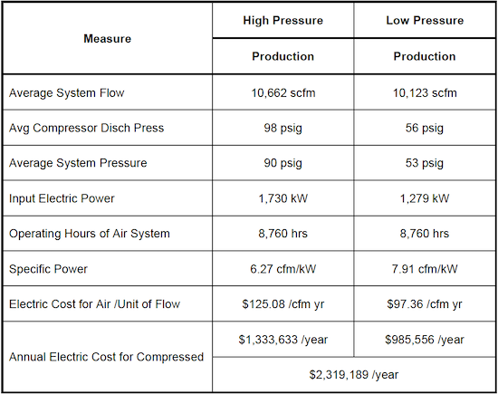
*Based upon on a blended electric rate of $0.088 per kWh and 8,760 hours/year.
Figure 1. Existing Compressed Air System Schematic
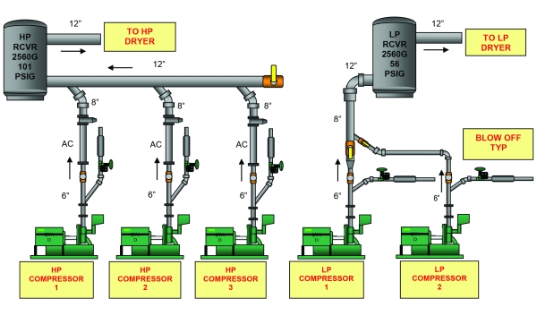
Table 3. Annual Load Profiles of Existing Air Compressors
Two Energy-Saving Compressed Air Projects Ideal for Maintenance Teams to Tackle
In almost every plant we visit, we find issues with compressed air condensate drains, either not working or wasting compressed air. We also find a “healthy” amount of compressed air leaks. After we’ve completed the system assessment, we share the results with the maintenance teams who help us repair/replace the condensate drains and the compressed air leaks. We then try to train them to make these two projects part of the on-going maintenance of the compressed air systems.
The ROIs of these two projects are very high and they fall comfortably within the skill sets of maintenance teams. Performing these two projects, at this plant, created energy savings of \$70,000 with a cost of approximately \$14,000.
Project #1: Replace/Repair Condensate Drains Wasting Compressed Air
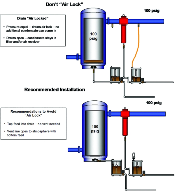
The configuration and performance of the condensate drains in the plant’s air compressor area and in the distribution system need to be modified. There were twenty-four (24) level activated, pneumatic actuated “no loss” automatic condensate drain valves. All drains have bottom entry connection. When this is done, the air above the condensate in the valve body has to be vented to avoid an “air lock” keeping the condensate from draining out. Twenty-one (21) of these valves vent to the atmosphere through an adjustable vent valve on top of the drain; which are set very high. On the low-pressure system, there are six drains which vent back to separator filter bodies and therefore, create no lost air.
The plant should repair or replace the 24 level activated pneumatic drains (leaking) with new level-activated drains, either electronic or pneumatic actuated at each point. In either scenario, it’s critical to re-pipe the condensate line to the top of the drain to eliminate the vent valve. Remove the vent valve and enlarge the entry hole on top to 5/8” size. Then run a 5/8” line to the threaded hole.
- A conservative estimate for the average vent loss = 10 cfm each
- The bypass line drains are leaking on the inside seals, one is medium size at 5 cfm and the other very large at 20 cfm
- A significant portion of these drains will have to be rebuilt in order to work properly. They are an excellent automatic drain.
- After replacement or rebuild, the drains should be installed with the condensate entering the top of the drain instead of the bottom. With top installation, you can eliminate the vent valve and there will be 165 cfm of high-pressure air saved and 50 cfm of low-pressure air saved (see Figure 2).
|
Total of number of drains to be reworked |
21 |
|
Total compressed air saved (50-hp low pressure / 165-hp high pressure) |
165 cfm |
|
Recoverable energy savings from air flow reduction |
\$188.78/cfm yr |
|
Total annual energy savings |
\$31,148/yr |
|
Cost per drain (materials and installation) |
\$500 each |
|
Cost of project (all drains) |
\$10,500 if replaced (less if reworked) |
Table 4: List of Condensate Drains to Repair/Replace
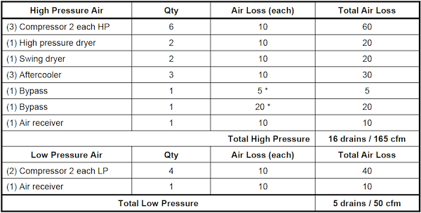
Figure 2.
Project #2: Identify/Repair Compressed Air Leaks and Set Up a Leak Management Program
Most plants can benefit from an ongoing air leak management program. Generally speaking, the most effective programs are those that involve the production supervisors and operators working in concert with the maintenance personnel. Accordingly, it is suggested that all programs consist of the following:
Short Term – Set up a continuing leak inspection by Maintenance Personnel so that for a while, each primary sector of the plant is inspected once each quarter to identify and repair leaks. A record should be kept of all findings, corrective measures, and overall results.
Long Term – Consider setting up programs to motivate the operators and supervisors to identify and repair leaks. One method that has worked well with many operations is to monitor/measure the air flow to each department and make each department responsible for identifying its air usage as a measurable part of the operating expense for that area. This usually works best when combined with an effective in-house training, awareness, and incentive program. You cannot manage it if you do not measure it!
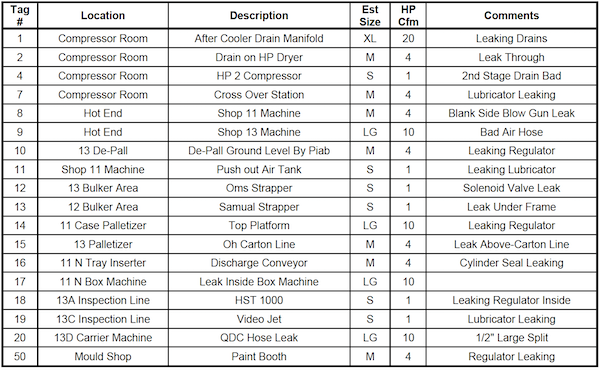
Compressed Air Leak Survey - A partial survey of compressed air leaks was conducted at the plant and 31 leaks were identified, quantified, tagged, and logged. Potential savings totaled 208 cfm for the 31 leaks that were identified. We estimate this will result in an energy savings of 495,884 kWh resulting in \$39,266 per year.
|
Number of leaks |
31 leaks |
|
Estimated reduction of air flow with proposed project |
208 cfm |
|
Recoverable savings from air flow reduction |
\$188.78/cfm yr |
|
Annual electric cost savings with proposed project |
\$39,266/year |
|
Total unit cost of leak repairs (\$25 materials per leak and \$75 labor per leak |
\$3,100 |
Table 4: List of Compressed Air Leaks to Repair
Conclusion
The goal of this article is to encourage plants to understand the energy costs of their compressed air system and to encourage their maintenance teams to be vigilant in the two project opportunities we find in almost every plant we visit. The two projects are to (1) repair/replace condensate drains wasting compressed air and (2) to perform compressed air leak surveys on a regular basis.
For more information on APenergy visit apenergy.com or call 740.862.4112.
To read similar Compressed Air System Assessment articles, visit https://www.airbestpractices.com/system-assessments.
For expert presentations, visit our Webinar Archive Section dedicated to Air Compressor Technology at https://www.airbestpractices.com/magazine/webinars.