In the initial article of this continuing series, we looked at the most common problem preventing multiple unit air compressor installation (2+), to do their job of matching supply to demand in an optimum manner. This article focused on piping design errors creating signals to the air compressor controls unrelated to anything happening on the production floor.
This article is going to identify two air compressor control situations that will preclude translating air use reduction in the production area into lower input energy into the air compressor.
The missing ingredient is often caused by a lack of understanding of the basic operating dynamics of each type of capacity control and air compressor.
Positive Displacement Air Compressors
Positive displacement air compressors are units where the inlet ambient air is swept into the compression chamber – sealed – and the compression chamber reduced creating the air compression to the desired discharge pressure. The most common types are reciprocal, rotary screw, rotary vane, rotary lobe and scroll.
All positive displacement air compressors, basically, react to an increase in discharge pressure with the volume (cfm) staying about the same and the input energy also increasing. Just the opposite happens when the pressure falls, similar volume (cfm), and lower input energy. This is an important dynamic to remember.
Capacity Controls for positive displacement air compressors can be placed into two categories:
Step Controls - Often two-step, also called full load/no load or cut in/cut out. The dynamics are (two-step) the compressor goes from idle or no load at the cut in pressure and runs at full capacity from that pressure until it senses the cut out or unload pressure (nominal 10 psid) where no air flows to the system until the system pressure falls to the cut in or load set point.
Flow Varying Controls - These have set points to hold and react almost instantly to any sensed change in discharge pressure. The most common types are Inlet Throttling, Variable Displacement and Variable Speed - all of which take action to adjust flow.
The operating dynamic is when they sense a rise in pressure above the set point they immediately start to deliver less air and when they sense a fall in pressure they immediately adjust to deliver more air.
Plant Audit with Two-Step and VSD Air Compressors
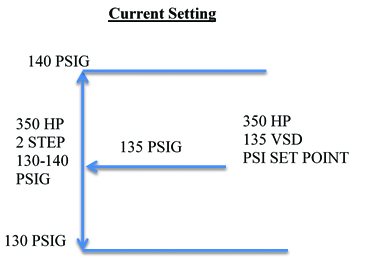
The plant has two oil free 350 HP rotary screw air compressors. One is a two-step or load/no load and the other is a VSD drive. The two units combined full load capacity is 2,617 cfm (VSD 1,329 scfm; fixed speed two-step 1,288 scfm) to supply a full production demand of 2,200 to 2,400 scfm and lower production levels of about 1,100 scfm. Accordingly, the two units were set up for the fixed speed (two-step) to run base load and the VSD unit in auto start trim. Both units enter an appropriately sized single compressed air storage tank from where the control signal is taken. Sounds like a good plan! The base load fixed-speed two-step control unit pressure settings are 130 psig to 140 psig and the VSD set point is 135 psig.

Figure 1
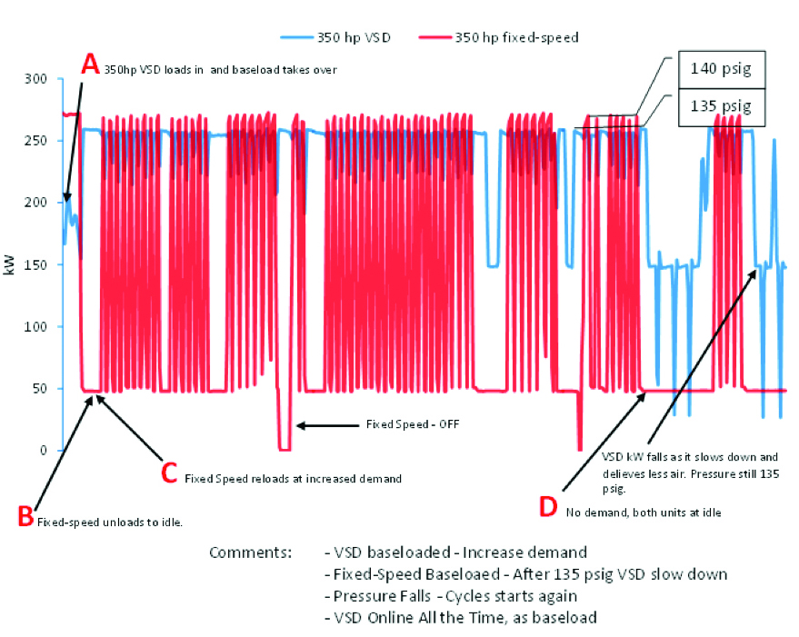
Figure 1 shows these settings and Figure 2 indicates how they are running together.

Figure 2. Click here to enlarge.
What Happens?
The fixed speed air compressor is “short cycling” two to three times per minute. The VSD is running loaded but backing down constantly when it runs base and the fixed speed loads in.
- The VSD set point is 135 psig and the fixed speed reaches 140 psig and unloads, the VSD is now in the base load.
- The fixed speed is at idle and the VSD is carrying the load demand (at 1,329 or less scfm).
- When the pressure falls 130 psig, the fixed speed loads in at full load. As the supply increases it stays fully loaded up to 140 psig. When the pressure exceeds 135 psig, the VSD backs off and the fixed speed continues at full load up to 140 psig, where it unloads and immediately reduces the delivered air by 1,288 scfm. Then the pressure falls rapidly until the cycle starts over again.
- The continued short cycling of the fixed speed goes on and on reducing its maximum flow capacity from 1,288 scfm to 50% or 644 scfm.
Air Compressor Master Controls to Prevent Control Gap – Webinar RecordingDownload the slides and watch the recording of the FREE webcast to learn:
|
Net Result
Since the two units cannot run together at full load rating (2,617 scfm) to deliver the required 2,200 – 2,400 scfm needed for production, the plant had to rent another air compressor. The maximum possible air volume would be less than 1,329 scfm from the VSD and only 644 scfm from the fixed speed, for a total of 1,973 scfm or less.
The Correction
Reset the VSD air compressor’s set point from midway between the operating band of the two-step control (130 – 140 psig). Reset the VSD target to 125 psig. When the pressure settings were adjusted on the fixed speed air compressor to 130 – 140 psig and a VSD set point of 125 psig, the fixed speed stayed at base load and the VSD became a very effective trim unit. The rental air compressor was returned.
Second Case Study - Operating Dynamics of Two Different Types of Air Compressors

Figure 3. Click here to enlarge.
Earlier we described the positive displacement operating dynamics with regards to sensed discharge pressure with a relatively stable volume and the input energy varying directly proportionate to the discharge pressure.
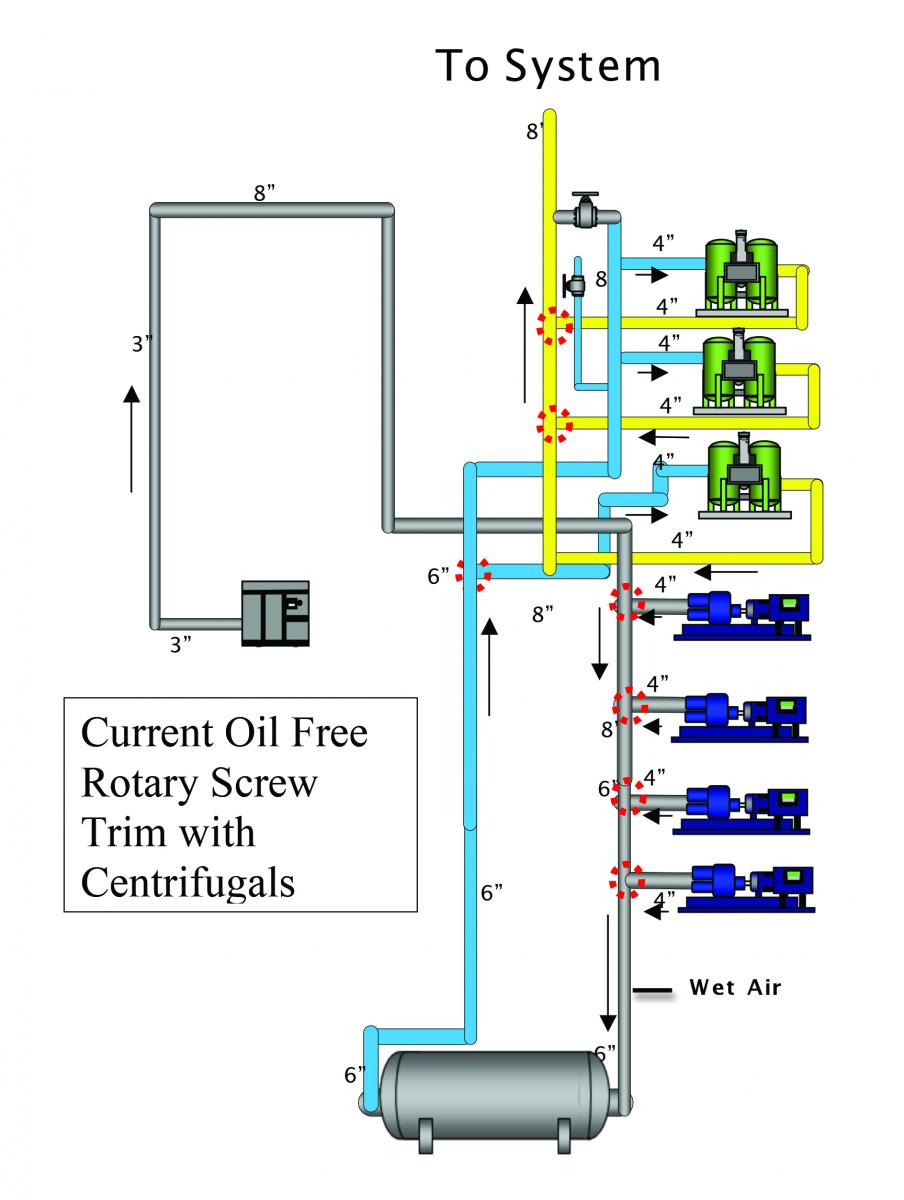
Now we put a positive displacement two-step rotary screw air compressor to run as a trim unit into a system with dynamic-type centrifugal air compressors. Centrifugal air compressors are also called mass flow units – with operating dynamics significantly different with regards to discharge pressure.
With dynamic air compressors, rising pressure also reduces flow at about the same percentage as the discharge pressure change but is inversely proportionate at about the same input power. Falling pressure usually increases flow at about the same input power. The important point here is each type (positive displacement or dynamic) reacts differently when the sensed discharge pressure changes even when at “full load.” This has to be taken into account in any air system management program, particularly when centrifugal compressors are involved.

Figure 4
What Actually Occurred
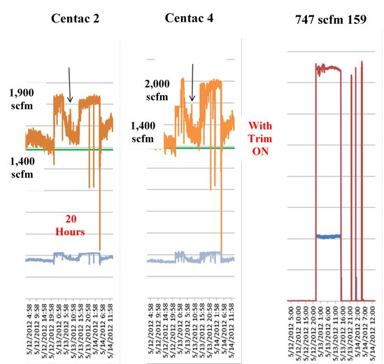
As soon as the variable speed drive trim air compressor (positive displacement) loaded into the system, pressure rose and the two 500 HP centrifugal (dynamic) units backed off in flow and the trim unit continued to stay on fully loaded for 20 hours (as shown in figure 4) until it was manually shut off. The trim unit added 747 scfm to the system while one centrifugal backed off from 1,900 scfm to 1,400 scfm and the other from 2,000 scfm to 1400 scfm. A total reduction of 1,100 scfm occurred. The total flow was reduced from 3,900 scfm to 2,800 scfm. Unfortunately, the centrifugal input KW stayed almost the same, while the trim unit added 159 KW. At the lower air supply the additional unneeded energy cost (.08 kW/h /8000hr/yr) was \$ 101,760 per year to serve the same demand.
Air Compressor Technology Monthly e-NewsletterWith a focus on Supply-Side Optimization, air compressor technologies and compressor control systems are profiled. System Assessment articles detail what compressor controls allow kWh consumption to match system demand. |
Corrective Actions
- Added directional angle entry from each centrifugal air compressor to the 8” header to minimize the turbulent backpressure.
- Installed an appropriately sized storage receiver (2,500 gal) for the after-cooled discharge air coming from the oil free screw trim unit. The set points are 95 psig to 105 psig.
- Installed a properly sized regulator to deliver the trim air at no greater than 98 psig. The regulator was selected to operate with less than 2 psig pressure drop. 95 psig was deemed an acceptable minimum system pressure.
- The regulated flow pressure of 98 psig operates below the full load set point of the centrifugal and will not push them back.
Conclusion
Whenever a positive displacement air compressor is entering the same header as a dynamic air compressor (in this case a centrifugal), the positive displacement air compressor load points have to be below the centrifugal compressor full load set point. This can be accomplished with proper set points or with a pressure regulator as shown.
Since this is an ongoing column, we encourage feedback on the discussions. In the next article, we will review products and technologies offering plants significant compressed air reduction opportunities - at low capital costs and usually with a rapid simple payback.
We hope you’ve found this interesting and look forward to your comments! Contact Hank van Ormer, email: hankvanormer@aol.com.
To read similar Air Compressor Control System Assessment articles visit www.airbestpractices.com/system-assessments/compressor-controls.
Read all the articles of this series:
Missed Demand-Side Opportunities Part 1 - Flow Restrictions from Pipe Headers
Missed Demand-Side Opportunities Part 3 - Controlling Open Blowing with Compressed Air
Missed Demand-Side Opportunities Part 6 - Look to AODD Pumps To Lower Compressed Air Demand
Missed - Demand-Side Opportunities Part 7 - The Importance of System Pressure Control


