Introduction
Technology is progressing at astounding rates in the control and monitoring of compressed air use. Many are familiar with the advances with improved technology in the compressed air supply. Such advancements as, proactive central air compressor controls to maintain optimum operation of multiple compressors to support ever changing air demands; improved drive systems such as VSD’s; magnetic bearing drives (centrifugals); and more efficient and reliable equipment taking advantage of modern manufacturing capability. These new technologies are very important in generating relative high energy cost savings, and are well promoted by the OEM equipment manufacturers.
This same trend of advanced technology use is happening and supporting many processes commonly used on the production floor. A common trait of these innovations and controls is they individually have very low initial cost and generate very solid savings - often with quick payback. And because of the low initial cost, these devices often aren’t supported with aggressive, knowledgeable sales representation at many operating locations.
When evaluating compressed air systems and looking for production area savings, we often recommend products which have been on the market for many years, and yet, are received by the operating plant personnel with surprise.
This series of articles is dedicated each month to showcase some important, but often undiscovered, technologies. We will describe the devices in detail and supply specific case studies when available. We believe this will offer affordable and easy to implement ideas to lower compressed air use and generate energy savings in many operations.
Can Compressed Air Supply Translate Lower Demand Into Input Energy Reductions?
Remember, compressed air is the most expensive utility in many plants. A minimum of about 8 hp electric input is required to produce 1-hp of work with compressed air. Before starting to evaluate the compressed air use reduction opportunities, discuss how to ensure your compressed air supply is set up properly to be able to effectively convert lower air demand into a commensurate reduction in input energy.
Experience has shown the savings in energy with production-floor opportunities often exceeds the most common supply side modifications. Due to the constant changing dynamics in the production areas, such factors as production changes, addition or reduction in production lines, and minor modifications that grow and can become major opportunities. The production areas require proper and meaningful monitoring of the KPI’s (key performance indicators) on a continuing basis, as well as the supply side.
In the case of the supply side, you want to be sure you are producing the needed compressed air at optimum efficiency. In the production area, you want to only use what you have identified as the optimum flow at the minimum pressure to ensure productivity and quality standards are met or exceeded.
This column does not allow enough room to fully identify all the supply side issues in equipment – storage, capacity controls, piping, condensate handling – that impact on the ability of the supply to effectively translate less demand side usage into lower input energy. However, here are some very common examples to illustrate the importance of this point. This is almost always the first step.
Flow Restrictions from Pipe Size and Configuration
Too high of velocities, due to undersized piping, and dead heads and crossing tees in multiple unit systems are caused by improper piping configuration. Together these restrictions can cause multiple (or even all the supply compressors) to run at part load. They cannot reach full load within an acceptable operating band.
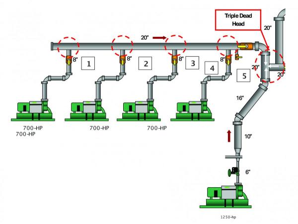
We will illustrate this with an example. The plant air system the plant air system in Figure 1 had a number of centrifugal compressors piped into a common header. Plant personnel felt most of the units were at full load as indicated by the master controller. However, as shown in the red dashed circles, the common header was experiencing crossing tee’s 1 through 4 and the triple dead head 5. The compressors are mass flow centrifugals and any sensed back-pressure or resistance to flow increased the mass flow which reduced the volume of inlet air delivered to the same mass flow.

Figure 1. Pipe Headers
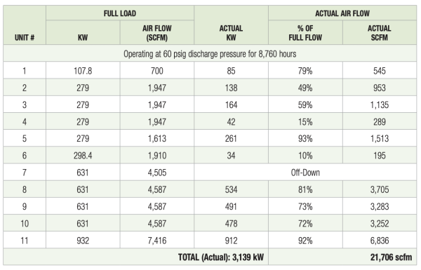
As shown in Figure 2, measured operating data of the 5 units in Figure 1 were running along with five other units feeding into the triple dead head. A total of ten units were loaded in with 31,241 scfm available, delivering 21,706 scfm at 60 psig at 3,319 kW.

Figure 2. Measured Actual Operation Conditions
This is an extreme example. It illustrates if you reduce the air demand on the demand side you may have little or no input energy reduction on the total electric power energy input. Some of these units are running in turndown but others are in blow off. Reduction in air flow demand from production will probably result in increased blow off and little or no change in input electric energy.
Implemented/Corrected Piping and Results
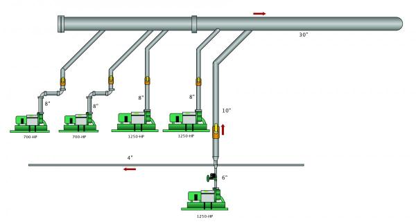
- Two older 700-hp units were replaced with new, higher efficiency 1,250-hp class units (also with greater turndown).
- The 20” collector header was increased to a 30” stainless steel, Schedule 10 header.
- All connections were angled directional entry to eliminate the turbulence from the crossing tees.
- The Triple Dead Head was eliminated.
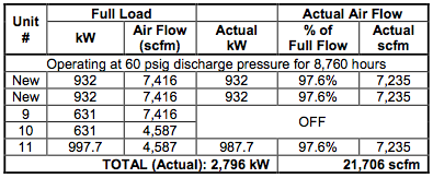
- The total load of 21,706 scfm was delivered by 2,796 kW with the implemented production air savings this load became the peak and full production was continuously carried by the three newer 1,250-hp units with the older 700-hp units in backup.
- At 21,706 scfm/60 psig, the original annualized input energy power was 3,139 kW. The energy 27,497,640 kWh at .09 kWh = \$2,474.788/year.
- With the piping and configuration change and two new units at the same flow and pressure would be:
- Input power 2,796 kW / 24,492,960 kWh @ .09 kWh = \$2,204,366/year
- An electrical energy savings of \$270,421/year
The new, more efficient, larger centrifugals probably improved the full load specific power 10%. The rest of the savings came from piing and system design modification.

Figure 3. After the piping correction, all of the units can deliver the full air supply to the system.

Figure 4. Corrected Operation Conditions.
A similar effect will happen regardless of the types of control when the local compressor capacity controls react to sensed changes in the interconnecting piping not related to actual production area operations but are generated in the compressor room.
When all of these types of issues are solved and the supply and demand sides of the total air systems are properly linked together, all reductions in air demand can be translated in lower input energy.
Since this is an ongoing column, we encourage feedback on the discussions. Next issue we will address some new products and air technologies which offer significant air reduction at low capital cost and usually a short simple payback.
We hope you’ve found this interesting and look forward to your comments! Contact Hank van Ormer, email: hankvanormer@aol.com.
To read similar Compressed Air Piping articles visit www.airbestpractices.com/system-assessments/piping-storage.
Read the next articles of this series:
Missed Demand-Side Opportunities Part 2 - Integrating Multiple Air Compressor Controls
Missed Demand-Side Opportunities Part 3 - Controlling Open Blowing with Compressed Air
Missed Demand-Side Opportunities Part 6 - Look to AODD Pumps To Lower Compressed Air Demand
Missed - Demand-Side Opportunities Part 7 - The Importance of System Pressure Control


